Example for Configuring iPCA to Implement End-to-End Packet Loss Measurement
iPCA Overview
Packet Conservation Algorithm for Internet (iPCA) technology is used to measure IP network performance. It directly marks service packets to implement network-level and device-level packet loss measurements.
In the all-IP era, various services sensitive to packet loss, such as voice and video services, are transmitted through an IP network. To detect packet loss and find out packet loss points on the network, Huawei developed iPCA technology. Huawei iPCA has the following characteristics:
- iPCA applies to both Layer 2 and Layer 3 networks.
- iPCA directly marks service packets to obtain the packet loss ratio and number of lost packets, without increasing loads on devices.
- iPCA supports packet loss statistics collection on multipoint-to-multipoint networks.
End-to-end packet loss measurement: Statistics are collected on edge devices that are a part of the transit network. This method is applicable to packet loss measurement for a specialized service flow, such as a voice flow and a video flow, on an enterprise network.
Configuration Notes
- For the applicable product models and versions of this example, see Applicable product models and versions.
- The prerequisite of network-level packet loss measurement is time synchronization between iPCA devices. Therefore, before configuring iPCA, configure NTP on the devices.
- In network-level packet loss measurement, the device can color known IP unicast packets but not MPLS packets or unknown IP unicast packets.
- Network-level packet loss measurement is based on target flows, you can specify target flows. If the packet content is modified (for example, NAT is performed on packets, packets are encapsulated in tunnels, and packet priority is changed), the device cannot precisely match the packets, so the measurement result may be inaccurate.
- In an MPLS L2VPN scenario, network-level packet loss measurement cannot be configured, including end-to-end packet loss measurement, regional network packet loss measurement, and network-level hop-by-hop packet loss measurement.
- In an MPLS L3VPN scenario, end-to-end packet loss measurement can be configured on private network interfaces of PEs, regional network packet loss measurement can be configured on the CEs, and network-level hop-by-hop packet loss measurement cannot be configured.
- End-to-end and regional network packet loss measurement support on-demand and proactive packet loss measurement. Network-level hop-by-hop packet loss measurement only supports on-demand packet loss measurement.
Networking Requirements
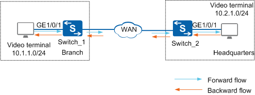
As shown in Figure 1, users in enterprise branches and headquarters encounter erratic display and delay when using the video conference service. The enterprise wants to obtain packet loss statistics of the video conference service and receive an alarm when the packet loss ratio exceeds 7% so that the network administrator can adjust service deployment in a timely manner.
Configuration Roadmap
Configure a service flow between video terminals as a target flow. It is a bidirectional symmetrical flow, so is divided into two unidirectional flows logically.
Configure Switch_1 as DCP1. Bind GE1/0/1 where the target flow passes to in-point ingress TLP of DCP1. Define instance 1 on DCP1 to collect statistics data of the target flow from TLPs.
Configure Switch_2 as DCP2. Bind GE1/0/1 where the target flow passes to out-point egress TLP of DCP2. Define instance 1 on DCP2 to collect statistics data of the target flow from TLPs.
Configure Switch_2 as the MCP to aggregate statistics data from DCP1 and DCP2 and export the statistics result. Configure packet loss alarm thresholds to help users predict network faults. When the packet loss ratio exceeds 7%, an alarm is reported; when the packet loss ratio falls back below 5%, a clear alarm is reported.
Retain the default values of color bit, measurement interval, and UDP port number used for communication between DCPs and MCP.

Before configuring iPCA to implement end-to-end packet loss measurement, ensure that static routes or a dynamic routing protocol has been configured to implement network connectivity between Switch_1 and Switch_2. The DCP ID or MCP ID of each switch must be an existing IP address, and the IP addresses must be reachable to each other.
Before configuring iPCA to implement end-to-end packet loss measurement, ensure that NTP has been configured to implement time synchronization between Switch_1 and Switch_2.
Procedure
- Configure Switch_1 as DCP1, set the DCP ID of Switch_1 to the router ID 10.1.1.1, and configure TLP 1.
<HUAWEI> system-view
[HUAWEI] sysname Switch_1
[Switch_1] nqa ipfpm dcp //Enable the global DCP function.
[Switch_1-nqa-ipfpm-dcp] dcp id 10.1.1.1 //Set the DCP ID to 10.1.1.1.
[Switch_1-nqa-ipfpm-dcp] instance 1 //Create measurement instance 1 on the DCP.
[Switch_1-nqa-ipfpm-dcp-instance-1] mcp 10.2.1.1 //Associate measurement instance 1 with an MCP.
[Switch_1-nqa-ipfpm-dcp-instance-1] flow bidirectional source 10.1.1.0 24 destination 10.2.1.0 24 //Configure the target flow in measurement instance 1 as a bidirectional symmetrical flow with the source address segment 10.1.1.0 and destination address segment 10.2.1.0.
[Switch_1-nqa-ipfpm-dcp-instance-1] tlp 1 in-point ingress //Set the TLP ID to 1 and configure the TLP to color the incoming target flow. The target flow arrives at the TLP.
[Switch_1-nqa-ipfpm-dcp-instance-1] quit
[Switch_1-nqa-ipfpm-dcp] quit
[Switch_1] interface gigabitethernet 1/0/1
[Switch_1-GigabitEthernet1/0/1] ipfpm tlp 1 //Bind the interface to the TLP.
[Switch_1-GigabitEthernet1/0/1] quit
[Switch_1] nqa ipfpm dcp
[Switch_1-nqa-ipfpm-dcp] instance 1
[Switch_1-nqa-ipfpm-dcp-instance-1] loss-measure enable continual //Enable continual packet loss measurement.
[Switch_1-nqa-ipfpm-dcp-instance-1] quit
[Switch_1-nqa-ipfpm-dcp] quit
- Configure Switch_2 as DCP2, set the DCP ID of Switch_2 to the router ID 10.2.1.1, and configure TLP 2.
<HUAWEI> system-view
[HUAWEI] sysname Switch_2
[Switch_2] nqa ipfpm dcp
[Switch_2-nqa-ipfpm-dcp] dcp id 10.2.1.1
[Switch_2-nqa-ipfpm-dcp] instance 1
[Switch_2-nqa-ipfpm-dcp-instance-1] mcp 10.2.1.1
[Switch_2-nqa-ipfpm-dcp-instance-1] flow bidirectional source 10.1.1.0 24 destination 10.2.1.0 24
[Switch_2-nqa-ipfpm-dcp-instance-1] tlp 2 out-point egress
[Switch_2-nqa-ipfpm-dcp-instance-1] quit
[Switch_2-nqa-ipfpm-dcp] quit
[Switch_2] interface gigabitethernet 1/0/1
[Switch_2-GigabitEthernet1/0/1] ipfpm tlp 2
[Switch_2-GigabitEthernet1/0/1] quit
[Switch_2] nqa ipfpm dcp
[Switch_2-nqa-ipfpm-dcp] instance 1
[Switch_2-nqa-ipfpm-dcp-instance-1] loss-measure enable continual
[Switch_2-nqa-ipfpm-dcp-instance-1] quit
[Switch_2-nqa-ipfpm-dcp] quit
- Configure Switch_2 as the MCP.
[Switch_2] nqa ipfpm mcp //Enable the global MCP function.
[Switch_2-nqa-ipfpm-mcp] mcp id 10.2.1.1 //Set the MCP ID to 10.2.1.1.
[Switch_2-nqa-ipfpm-mcp] instance 1 //Create measurement instance 1 on the MCP.
[Switch_2-nqa-ipfpm-mcp-instance-1] dcp 10.1.1.1 //Associate measurement instance 1 with the DCP whose ID is 10.1.1.1.
[Switch_2-nqa-ipfpm-mcp-instance-1] dcp 10.2.1.1 //Associate measurement instance 1 with the DCP whose ID is 10.2.1.1.
[Switch_2-nqa-ipfpm-mcp-instance-1] loss-measure ratio-threshold upper-limit 7 lower-limit 5 //Set the packet loss alarm threshold to 7% and clear alarm threshold to 5%.
[Switch_2-nqa-ipfpm-mcp-instance-1] quit
[Switch_2-nqa-ipfpm-mcp] quit
[Switch_2] quit
- Verify the configuration.
# Run the display ipfpm statistic-type loss instance 1 command on Switch_2 that functions as the MCP to view the packet loss measurement result.
<Switch_2> display ipfpm statistic-type loss instance 1

Latest loss statistics of forward flow:
Unit: p - packet, b - byte
------------------------------------------------------------------------------------------
 Period               Loss(p)              LossRatio(p)  Loss(b)              LossRatio(b)
------------------------------------------------------------------------------------------
 127636768            381549               4.514649%     40444194             4.514649%
 127636767            381528               4.514620%     40441968             4.514620%
 127636766            381318               4.514996%     40419708             4.514996%
 127636765            381192               4.514686%     40406352             4.514686%
 127636764            381381               4.514679%     40426386             4.514679%
 127636763            381402               4.514748%     40428612             4.514748%
 127636762            381081               4.514797%     40394586             4.514797%
 127636761            381324               4.514702%     40420344             4.514702%
 127636760            381549               4.514870%     40444194             4.514870%
 127636759            381066               4.514638%     40392996             4.514638%
 127636758            381570               4.514836%     40446420             4.514836%
 127636757            382452               4.514757%     40539912             4.514757%

Latest loss statistics of backward flow:
Unit: p - packet, b - byte
------------------------------------------------------------------------------------------
 Period               Loss(p)              LossRatio(p)  Loss(b)              LossRatio(b)
------------------------------------------------------------------------------------------
 127636768            381087               4.513306%     40395222             4.513306%
 127636767            381129               4.513384%     40399674             4.513384%
 127636766            381465               4.513444%     40435290             4.513444%
 127636765            381087               4.513222%     40395222             4.513222%
 127636764            381045               4.513272%     40390770             4.513272%
 127636763            381381               4.513364%     40426386             4.513364%
 127636762            381276               4.513435%     40415256             4.513435%
 127636761            380961               4.513280%     40381866             4.513280%
 127636760            381339               4.513574%     40421934             4.513574%
 127636759            381045               4.513270%     40390770             4.513270%
 127636758            381088               4.513226%     40395328             4.513226%
 127636757            382409               4.513464%     40535354             4.513464%
Configuration Files
Configuration file of Switch_1
#
sysname Switch_1
#
interface GigabitEthernet1/0/1
 ipfpm tlp 1
#
nqa ipfpm dcp
 dcp id 10.1.1.1
 instance 1
  mcp 10.2.1.1
  flow bidirectional source 10.1.1.0 24 destination 10.2.1.0 24
  tlp 1 in-point ingress
  loss-measure enable continual
#
return
Configuration file of Switch_2
#
sysname Switch_2
#
interface GigabitEthernet1/0/1
 ipfpm tlp 2
#
nqa ipfpm dcp
 dcp id 10.2.1.1
 instance 1
  mcp 10.2.1.1
  flow bidirectional source 10.1.1.0 24 destination 10.2.1.0 24
  tlp 2 out-point egress
  loss-measure enable continual
#
nqa ipfpm mcp
 mcp id 10.2.1.1
 instance 1
  dcp 10.1.1.1
  dcp 10.2.1.1
  loss-measure ratio-threshold upper-limit 7.000000 lower-limit 5.000000
#
return
Applicable product models and versions
Product |
Product Model |
Software Version |
|---|---|---|
S5700 |
S5720-HI |
V200R006C00, V200R007(C00&C10), V200R008C00, V200R009C00, V200R010C00, V200R011C00, V200R011C10, V200R012C00, V200R013C00, V200R019C00, V200R019C10 |
S5730-HI |
V200R012C00, V200R013C00, V200R019C00, V200R019C10 |
|
S5731-H |
V200R013C02, V200R019C00, V200R019C10 |
|
S5731-S, S5731S-S |
V200R019C00, V200R019C10 |
|
S5731S-H |
V200R019C00, V200R019C10 |
|
S5732-H |
V200R019C00, V200R019C10 |
|
S6700 |
S6720-HI |
V200R012C00, V200R013C00, V200R019C00, V200R019C10 |
S6730-H |
V200R013C02, V200R019C00, V200R019C10 |
|
S6730S-H |
V200R019C10 |
|
S6730-S, S6730S-S |
V200R019C00, V200R019C10 |
|
S7700 |
S7703, S7706, S7712 |
V200R006C00, V200R007C00, V200R008C00, V200R009C00, V200R010C00, V200R011C10, V200R012C00, V200R013C00, V200R013C02, V200R019C00, V200R019C10 |
S7703 PoE |
V200R013C00, V200R019C00, V200R019C10 |
|
S7706 PoE |
V200R013C00, V200R019C00, V200R019C10 |
|
S9700 |
S9703, S9706, S9712 |
V200R006C00, V200R007C00, V200R008C00, V200R009C00, V200R010C00, V200R011C10, V200R012C00, V200R013C00 |
For modular switches, only the X series cards support iPCA.