Locating Faults Using iPCA and Point by Point Detect Configured on eSight
iPCA Overview
Packet Conservation Algorithm for Internet (iPCA) technology is used to measure IP network performance. It directly marks service packets to implement network-level and device-level packet loss measurements.
In the all-IP era, various services sensitive to packet loss, such as voice and video services, are transmitted through an IP network. To detect packet loss and find out packet loss points on the network, Huawei developed iPCA technology. Huawei iPCA has the following characteristics:
- iPCA applies to both Layer 2 and Layer 3 networks.
- iPCA directly marks service packets to obtain the packet loss ratio and number of lost packets, without increasing loads on devices.
- iPCA supports packet loss statistics collection on multipoint-to-multipoint networks.
Configuring iPCA on eSight and delivering iPCA configuration to the switch can simplify configurations and make statistics result visible. Point by Point Detect can implement network-level hop-by-hop packet loss measurement. If packet loss occurs, the packet loss point is quickly detected.
Configuration Notes
- For the applicable product models and versions of this example, see Applicable products and versions.
- This example shows how to configure iPCA on eSight to collect statistics on lost packets hop by hop. In this example, the switch version is V200R008C00 and eSight version is V300R005C00.
- The prerequisite of network-level packet loss measurement is time synchronization between iPCA devices. Therefore, before configuring iPCA, configure NTP on the devices.
- In network-level packet loss measurement, the device can color known IP unicast packets but not MPLS packets or unknown IP unicast packets.
- Network-level packet loss measurement is based on target flows, you can specify target flows. If the packet content is modified (for example, NAT is performed on packets, packets are encapsulated in tunnels, and packet priority is changed), the device cannot precisely match the packets, so the measurement result may be inaccurate.
- In an MPLS L2VPN scenario, network-level packet loss measurement cannot be configured, including end-to-end packet loss measurement, regional network packet loss measurement, and network-level hop-by-hop packet loss measurement.
- In an MPLS L3VPN scenario, end-to-end packet loss measurement can be configured on private network interfaces of PEs, regional network packet loss measurement can be configured on the CEs, and network-level hop-by-hop packet loss measurement cannot be configured.
- End-to-end and regional network packet loss measurement support on-demand and proactive packet loss measurement. Network-level hop-by-hop packet loss measurement only supports on-demand packet loss measurement.
Networking Requirements
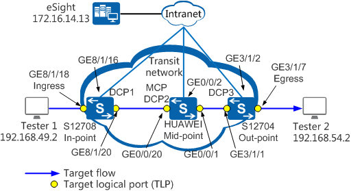
On the network shown in Figure 1, Tester 1 repeatedly sends packets to Tester 2, and a QoS policy is configured in the outbound direction of GE0/0/1 on the device HUAWEI to discard some packets of the target flow. iPCA is configured on eSight. You can see the packet loss point in the topology view. In practice, you can quickly detect the failure point using this function.
Data Planning
Item |
Interface |
VLAN ID |
IP Address |
|---|---|---|---|
S12708 (In-point) |
GE8/1/16 |
100 |
VLANIF100: 172.16.14.112/24 |
GE8/1/18 |
20 |
VLANIF20: 192.168.49.1/24 |
|
GE8/1/20 |
21 |
VLANIF21: 192.168.52.1/24 |
|
HUAWEI (Mid-point) |
GE0/0/1 |
22 |
VLANIF22: 192.168.53.1/24 |
GE0/0/2 |
200 |
VLANIF200: 172.16.9.90/24 |
|
GE0/0/20 |
21 |
VLANIF21: 192.168.52.2/24 |
|
S12704 (Out-point) |
GE3/1/1 |
22 |
VLANIF22: 192.168.53.2/24 |
GE3/1/2 |
200 |
VLANIF200: 172.16.9.91/24 |
|
GE3/1/7 |
23 |
VLANIF23: 192.168.54.1/24 |
Configuration Roadmap
- Configure the switches S12708, HUAWEI, and S12704:
- Allocate VLANs based on interfaces and assign IP addresses to VLANIF interfaces.
- Configure routes.
- Configure SNMP and Telnet.
- Configure NTP.
- Configure the MCP (HUAWEI).
- Configure the eSight:
- Add Resource.
- Configure iPCA.
- Check real-time statistics before QoS policy is delivered.
- Configure the QoS policy.
- Check real-time statistics after QoS policy is delivered.
- Perform Point by Point Detect.
Procedure
- Configure the switches S12708, HUAWEI, and S12704.
- Configure NTP.

The iPCA devices must have time synchronized; therefore, NTP must be configured before iPCA is deployed.
# Configure the HUAWEI as the NTP server.[HUAWEI] ntp-service source-interface Vlanif 21 //Set the local source interface that sends NTP packets to Vlanif21. [HUAWEI] ntp-service refclock-master 1 [HUAWEI] undo ntp-service server disable //Configure the switch as the NTP server.
# Configure the S12708 as the NTP client.[S12708] ntp-service unicast-server 192.168.52.2 //Set the IP address of the NTP server to 192.168.52.2.# Configure the S12704 as the NTP client.[S12704] ntp-service unicast-server 192.168.52.2
# Check whether time between the three switches is synchronized. For example, verify time synchronization on the S12704.[S12704] display ntp-service status clock status: synchronized //The local clock has been synchronized with the NTP server. clock stratum: 2 reference clock ID: 192.168.52.2 //The IP address of the NTP server is 192.168.52.2. nominal frequency: 100.0000 Hz actual frequency: 100.0000 Hz clock precision: 2^17 clock offset: 19.8577 ms root delay: 2.25 ms root dispersion: 28.71 ms peer dispersion: 10.94 ms reference time: 20:18:31.232 UTC Dec 13 2016(DBFAD617.3B928E0C) synchronization state: clock synchronized
- Configure NTP.
- Configure the eSight.
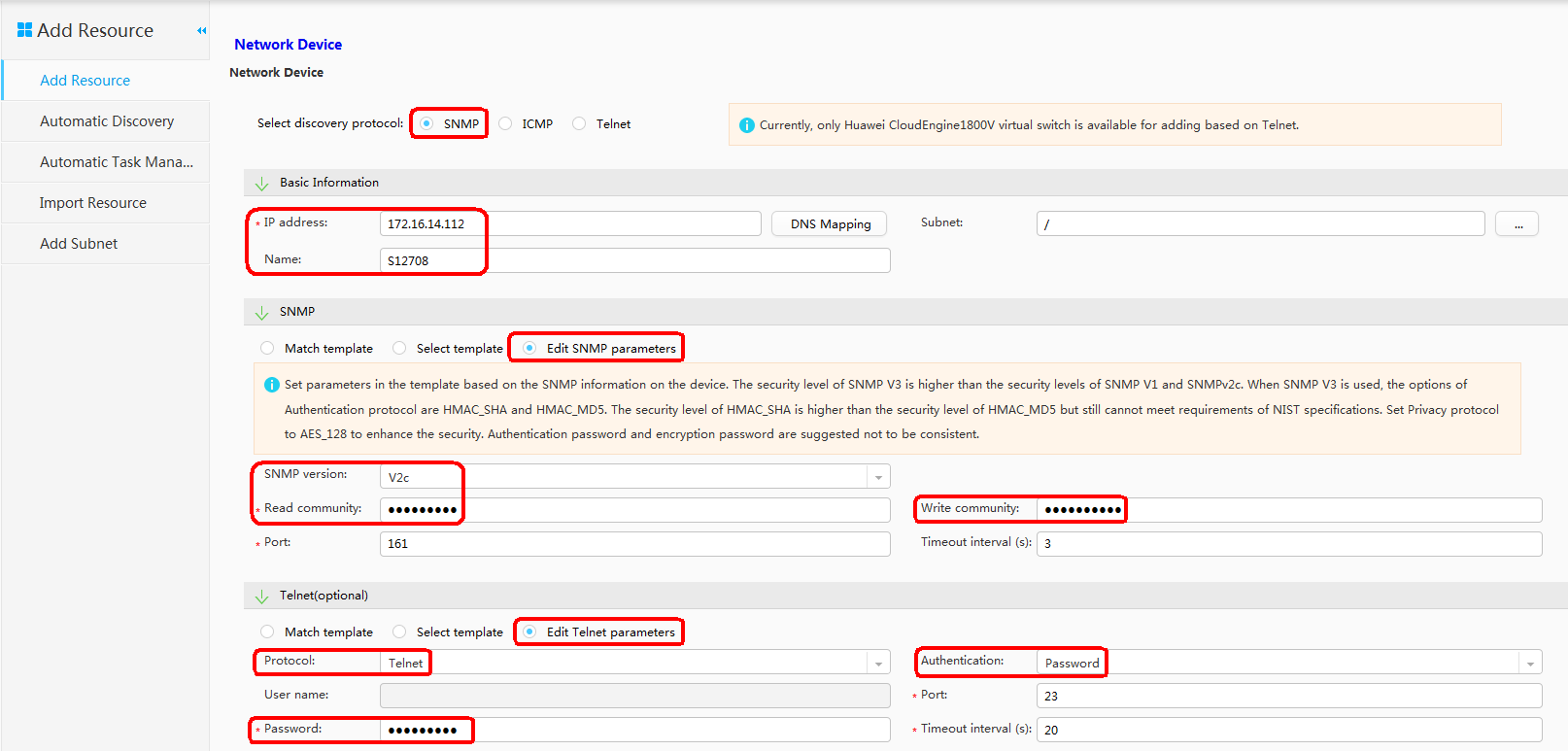
- Add Resource.
# In this example, the eSight added S12708. The processes of adding HUAWEI and S12704 are similar, and are not mentioned here. Choose in the upper navigation pane of the eSight. Configure the S12708 according to the figure. Set the Read community to public123, Write community to private123, and Password to huawei123, and click OK.
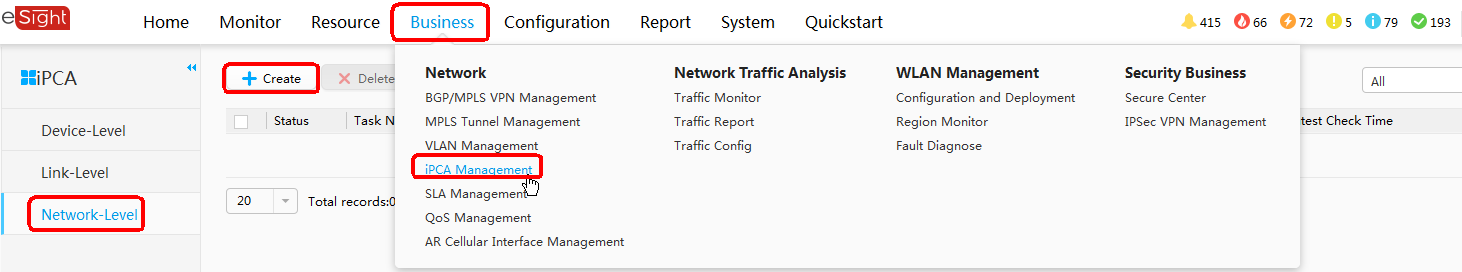
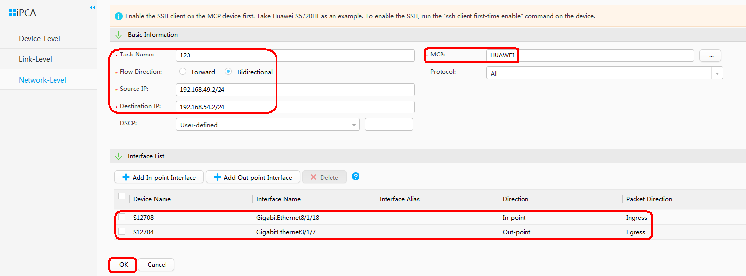
- Configure iPCA.
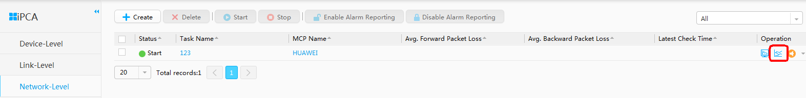
# Choose on the eSight homepage. Click on the left side and click on the right side to create the task . Configure the task according to the figure.
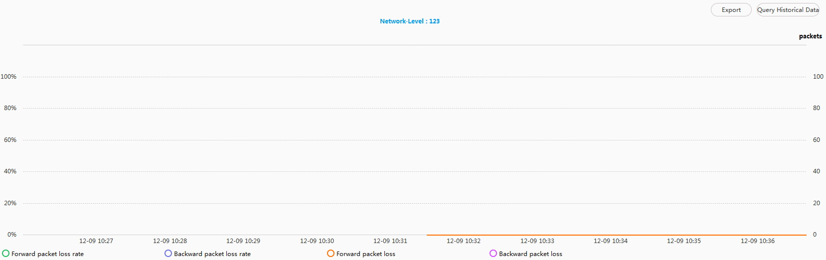
- Check real-time statistics before QoS policy is delivered.
# Click the Query Real-time Data icon. In normal situations, there should be no packet loss between S12708 and S12704.
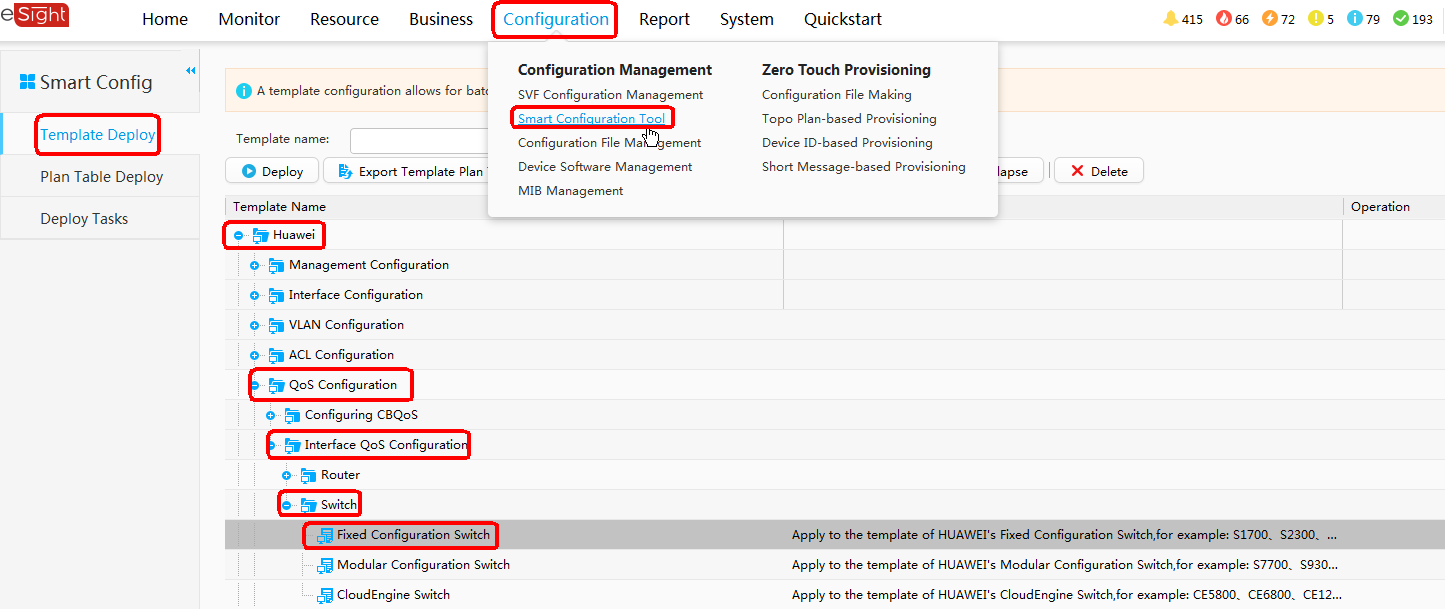
- Configure the QoS policy.
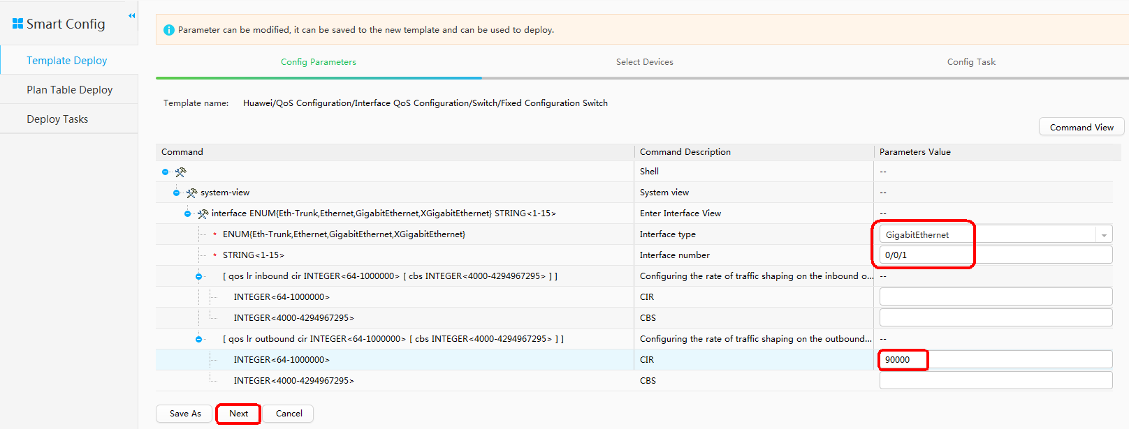
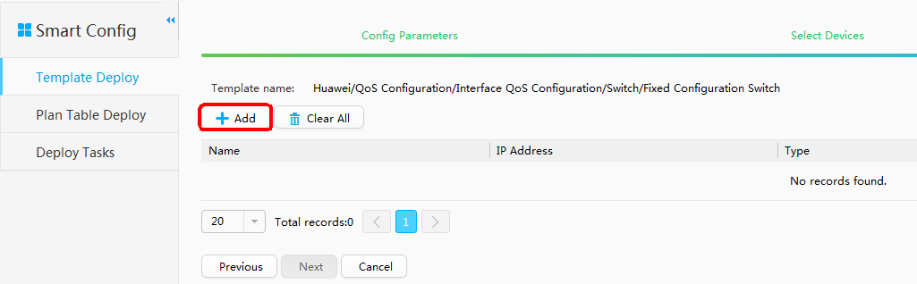
- Choose on the eSight homepage. Click on the left side and choose on the right side. Double-click Fixed Configuration Switch, after the configuration is complete, click Next.
In this example, the QoS policy is used to simulate packet loss in order to show the hop-by-hop detection on the eSight. In practice, the QoS policy is not required.
Click Add.
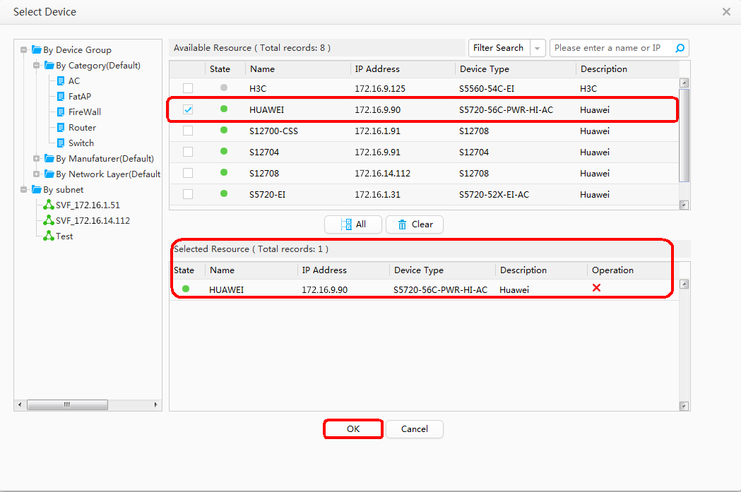
Select HUAWEI (172.16.9.90) and click OK.
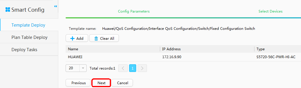
Click Next.
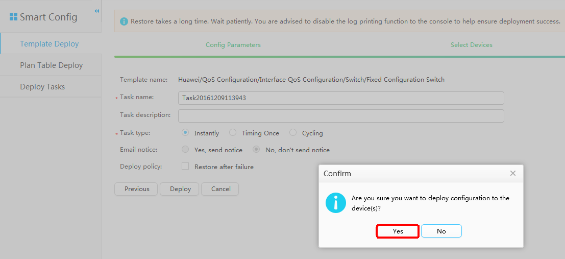
Select Instantly for Task type and click Deploy.
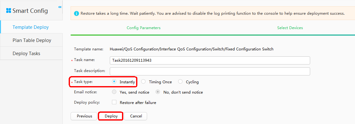
Click Yes in the displayed dialog box to deliver the QoS policy.
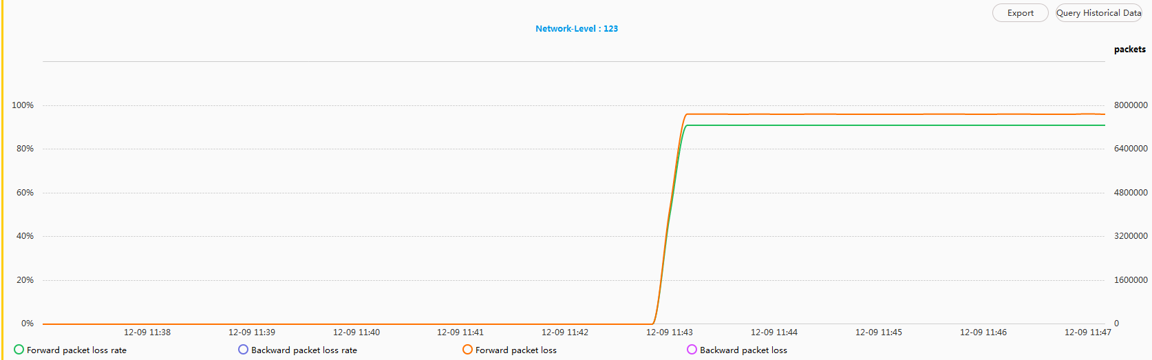
- Check real-time statistics after QoS policy is delivered.
# Click the Query Real-time Data icon. After the QoS policy is delivered, there is a severe packet loss between S12708 and S12704.
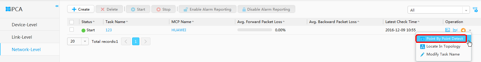
- Perform Point by Point Detect.
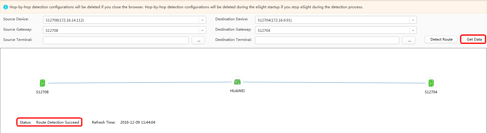
When packet loss has happened, check each segment on the path to determine the packet loss point. Click Point by Point Detect.
Click Detect Route.
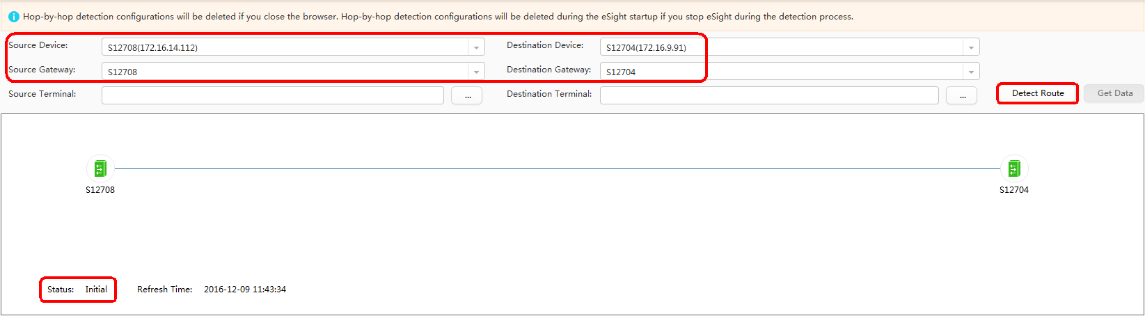
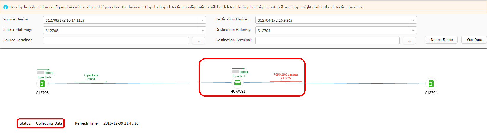
When the status changes to Route Detection Succeed, click Get Data.
When the status changes to Collecting Data, you can see that the packet loss point between HUAWEI and S12704. Check the interface configurations. You can find that the packet loss point is on GE0/0/1 of HUAWEI, which is connected to S12704.
- Add Resource.
Configuration Files
- S12708 configuration file
#
sysname S12708
#
vlan batch 20 to 21 100
#
telnet server enable
#
ntp-service server disable
ntp-service ipv6 server disable
ntp-service unicast-server 192.168.52.2
#
interface Vlanif20
 ip address 192.168.49.1 255.255.255.0
#
interface Vlanif21
 ip address 192.168.52.1 255.255.255.0
#
interface Vlanif100
 ip address 172.16.14.112 255.255.255.0
#
interface GigabitEthernet8/1/16
 port link-type trunk
 port trunk pvid vlan 100
 port trunk allow-pass vlan 100
#
interface GigabitEthernet8/1/18
 port link-type access
 port default vlan 20
 ipfpm tlp 9
#
interface GigabitEthernet8/1/20
 port link-type trunk
 port trunk pvid vlan 21
 port trunk allow-pass vlan 21
 ipfpm tlp 15
#
ospf 1
 area 0.0.0.0
  network 192.168.49.0 0.0.0.255
  network 192.168.52.0 0.0.0.255
#
ip route-static 0.0.0.0 0.0.0.0 172.16.14.1
#
snmp-agent
snmp-agent community read cipher %^%#eDeVP&K\5A,]8f$D4/C4y%h"2<w%4Y$*&bU2\$lXx7tHL5)y'W-<~SfGIFv98C):GzYCO[\,G"@e!%^%#
snmp-agent community write cipher %^%##t3d@h\k-4/vJqQPWih@"W+^MOv%RI@W056.3&oM"DiQY(m)C04qqcG*rl#Ps%`>4HF-O'Rb)eD,W.X$%^%#
snmp-agent sys-info version all
#
nqa ipfpm dcp
 dcp id 172.16.14.112
 mcp 172.16.9.90
 instance 4
  flow bidirectional source 192.168.49.0 24 destination 192.168.54.0 24
  tlp 9 in-point ingress
  tlp 15 mid-point flow bidirectional egress
  loss-measure enable continual
#
user-interface vty 0 4
 authentication-mode password
 user privilege level 15
 set authentication password cipher $1c$I",iD'G$4>$B+Ep3[K9!NFvdO$9s>B7E%q$T~E3l~s@dF6)OLEF$
 protocol inbound telnet
#
return
- HUAWEI configuration file
# vlan batch 21 to 22 200 # telnet server enable # ntp-service ipv6 server disable ntp-service source-interface Vlanif21 ntp-service refclock-master 1 # interface Vlanif21 ip address 192.168.52.2 255.255.255.0 # interface Vlanif22 ip address 192.168.53.1 255.255.255.0 # interface Vlanif200 ip address 172.16.9.90 255.255.255.0 # interface GigabitEthernet0/0/1 port link-type trunk port trunk pvid vlan 22 port trunk allow-pass vlan 22 ipfpm tlp 17 qos lr inbound cir 90000 cbs 11250000 # interface GigabitEthernet0/0/2 port link-type trunk port trunk pvid vlan 200 port trunk allow-pass vlan 200 # interface GigabitEthernet0/0/20 port link-type trunk port trunk pvid vlan 21 port trunk allow-pass vlan 21 ipfpm tlp 16 # ospf 1 area 0.0.0.0 network 192.168.52.0 0.0.0.255 network 192.168.53.0 0.0.0.255 # ip route-static 0.0.0.0 0.0.0.0 172.16.9.1 # snmp-agent snmp-agent community read cipher %^%#iPPB,G@4D4j/`oS}suRKw2l(Apd"z0Bx.3"7B(&A+b#v>G;4k~yOHWNbyB,7\y5fF!=E1*e{m~#kI28J%^%# snmp-agent community write cipher %^%#+;QU),%}n:K`=v#EbI9M>f&PU+lo'C7[GMCx4^!#u^".-$l:@6b\tcB*dI"C@[ga+UgK~C<xO1F'FVm.%^%# snmp-agent sys-info version all # ssh client first-time enable # nqa ipfpm dcp dcp id 172.16.9.90 mcp 172.16.9.90 instance 4 flow bidirectional source 192.168.49.0 24 destination 192.168.54.0 24 tlp 16 mid-point flow bidirectional ingress tlp 17 mid-point flow bidirectional egress # nqa ipfpm mcp mcp id 172.16.9.90 instance 4 dcp 172.16.9.90 dcp 172.16.9.91 dcp 172.16.14.112 ach 1 flow forward in-group dcp 172.16.14.112 tlp 9 out-group dcp 172.16.14.112 tlp 15 ach 2 flow forward in-group dcp 172.16.14.112 tlp 15 out-group dcp 172.16.9.90 tlp 16 ach 3 flow forward in-group dcp 172.16.9.90 tlp 16 out-group dcp 172.16.9.90 tlp 17 ach 4 flow forward in-group dcp 172.16.9.90 tlp 17 out-group dcp 172.16.9.91 tlp 18 ach 5 flow forward in-group dcp 172.16.9.91 tlp 18 out-group dcp 172.16.9.91 tlp 10 ach 6 flow backward in-group dcp 172.16.9.91 tlp 10 out-group dcp 172.16.9.91 tlp 18 ach 7 flow backward in-group dcp 172.16.9.91 tlp 18 out-group dcp 172.16.9.90 tlp 17 ach 8 flow backward in-group dcp 172.16.9.90 tlp 17 out-group dcp 172.16.9.90 tlp 16 ach 9 flow backward in-group dcp 172.16.9.90 tlp 16 out-group dcp 172.16.14.112 tlp 15 ach 10 flow backward in-group dcp 172.16.14.112 tlp 15 out-group dcp 172.16.14.112 tlp 9 # user-interface vty 0 4 authentication-mode password user privilege level 15 set authentication password cipher $1c$I",iD'G$4>$B+Ep3[K9!NFvdO$9s>B7E%q$T~E3l~s@dF6)OLEF$ protocol inbound telnet # return - S12704 configuration file
#
sysname S12704
#
vlan batch 22 to 23 200
#
telnet server enable
#
ntp-service server disable
ntp-service ipv6 server disable
ntp-service unicast-server 192.168.52.2
#
interface Vlanif22
 ip address 192.168.53.2 255.255.255.0
#
interface Vlanif23
 ip address 192.168.54.1 255.255.255.0
#
interface Vlanif200
 ip address 172.16.9.91 255.255.255.0
#
interface GigabitEthernet3/1/1
 port link-type trunk
 port trunk pvid vlan 22
 port trunk allow-pass vlan 22
 ipfpm tlp 18
#
interface GigabitEthernet3/1/2
 port link-type trunk
 port trunk pvid vlan 200
 port trunk allow-pass vlan 200
#
interface GigabitEthernet3/1/7
 port link-type access
 port default vlan 23
 ipfpm tlp 10
#
ospf 1
 area 0.0.0.0
  network 192.168.53.0 0.0.0.255
  network 192.168.54.0 0.0.0.255
#
ip route-static 0.0.0.0 0.0.0.0 172.16.9.1
#
snmp-agent
snmp-agent community read cipher %^%#$}!qC&[UR$>5i_1gJL*Q_HunMK88-JL%l[(1ABRP[5}n9dBKz%OM>QLRH+7IeAePK8u8$@/$xZQVHFxC%^%#
snmp-agent community write cipher %^%#RD%C78I\F&'asu>7~/P-ah]H-zwjMW}B7w3qJ8B&Gs/jF8*d%$aV^1H.g;j+-><p8//Y3;i4#j5Ro7w-%^%#
snmp-agent sys-info version all
#
nqa ipfpm dcp
 dcp id 172.16.9.91
 mcp 172.16.9.90
 instance 4
  flow bidirectional source 192.168.49.0 24 destination 192.168.54.0 24
  tlp 10 out-point egress
  tlp 18 mid-point flow bidirectional ingress
  loss-measure enable continual
#
user-interface vty 0 4
 authentication-mode password
 user privilege level 15
 set authentication password cipher $1c$I",iD'G$4>$B+Ep3[K9!NFvdO$9s>B7E%q$T~E3l~s@dF6)OLEF$
 protocol inbound telnet
#
return
Applicable products and versions
Product |
Product Model |
Software Version |
|---|---|---|
S5700 |
S5720-HI |
V200R008C00, V200R009C00, V200R010C00, V200R011C00, V200R011C10, V200R012C00, V200R013C00, V200R019C00, V200R019C10 |
S5730-HI |
V200R012C00, V200R013C00, V200R019C00, V200R019C10 |
|
S5731-H |
V200R013C02, V200R019C00, V200R019C10 |
|
S5731-S, S5731S-S |
V200R019C00, V200R019C10 |
|
S5731S-H |
V200R019C00, V200R019C10 |
|
S5732-H |
V200R019C00, V200R019C10 |
|
S6700 |
S6720-HI |
V200R012C00, V200R013C00, V200R019C00, V200R019C10 |
S6730-H |
V200R013C02, V200R019C00, V200R019C10 |
|
S6730S-H |
V200R019C10 |
|
S6730-S, S6730S-S |
V200R019C00, V200R019C10 |
|
S7700 |
S7703, S7706, S7712 |
V200R008C00, V200R009C00, V200R010C00, V200R011C10, V200R012C00, V200R013C00, V200R013C02, V200R019C00, V200R019C10 |
S7703 PoE |
V200R013C00, V200R019C00, V200R019C10 |
|
S7706 PoE |
V200R013C00, V200R019C00, V200R019C10 |
|
S9700 |
S9703, S9706, S9712 |
V200R008C00, V200R009C00, V200R010C00, V200R011C10, V200R012C00, V200R013C00 |