Example for Setting Up a Stack Using Stack Cards (V200R001 and Later Versions)
Networking Requirements
A new enterprise network needs to provide sufficient ports for access devices, and the network structure should be simple to facilitate configuration and management.
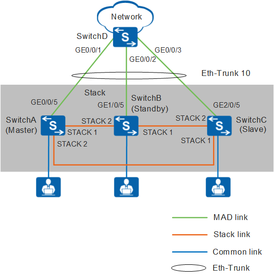
As shown in Figure 1, SwitchA, SwitchB, and SwitchC need to set up a stack in a ring topology and connect to SwitchD through an inter-device Eth-Trunk. SwitchA, SwitchB, and SwitchC are the master, standby, and slave switches respectively, with stack IDs of 0, 1, and 2 and stack priorities of 200, 100, and 100. As the three switches function as one logical device on the network, the number of ports is increased and network management and maintenance are simplified.
In this example, S5700-EIs set up a stack.
Configuration Roadmap
Power off SwitchA, SwitchB, and SwitchC, install an ES5D00ETPC00 stack card on each switch, and then power on the three switches.

The ES5D00ETPC00 stack card does not support hot swap. You need to power off a switch before installing the stack card on the switch.
You can perform software configurations only after installing a stack card on the switch.
Enable the stacking function.
Configure stack IDs and stack priorities for member switches to facilitate device management and identification.
Power off SwitchA, SwitchB, and SwitchC, connect physical member ports using PCIe cables, and then power on the three switches.
Configure an inter-device Eth-Trunk to increase reliability and uplink bandwidth.
Configure multi-active detection (MAD) in relay mode to ensure network availability when the stack splits. The stack split detection mechanism is called dual-active detection (DAD) in V200R002 and earlier versions and MAD in later versions.
Procedure
- Turn off power supplies of SwitchA, SwitchB, and SwitchC, install an ES5D00ETPC00 stack card on each switch, and then power on the three switches.
- Enable the stacking function. This function is enabled by default.
- Configure stack IDs and stack priorities. The default stack ID is 0, and the default stack priority is 100.
[SwitchA] stack slot 0 priority 200 //Set the stack priority of the master switch to 200, which is larger than those of other member switches, and use the default stack ID 0.
[SwitchB] stack slot 0 renumber 1 //Use the default stack priority 100 and set the stack ID to 1.
[SwitchC] stack slot 0 renumber 2 //Use the default stack priority 100 and set the stack ID to 2.
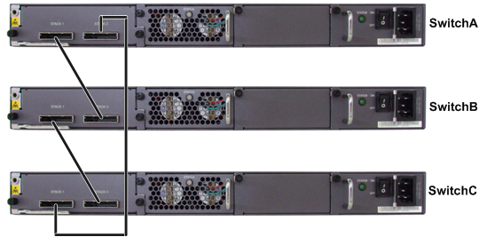
- Turn off power supplies of SwitchA, SwitchB, and SwitchC, connect physical member ports using PCIe cables as shown in Figure 2, and then power on the three switches.
- Run the save command to save the configurations before you power off the switches.
- STACK 1 port of one switch must be connected to STACK 2 port of another switch. Otherwise, the stack cannot be set up.
- To ensure that a stack can be set up successfully, you are advised to perform operations in the following sequence. First, power on the switch that you want to specify as the master switch. In this example, SwitchA becomes the master switch after you complete the following operations.
- Power off SwitchA, SwitchB, and SwitchC.
- Connect SwitchA and SwitchB with a stack cable.
- Power on and start SwitchA and then power on SwitchB.
- Check whether SwitchA and SwitchB set up a stack successfully. For details, see step 5.
- Connect SwitchC to SwitchB and SwitchA using stack cables and then power on SwitchC.
- Check whether SwitchA, SwitchB, and SwitchC set up a stack successfully. For details, see step 5.
- Check whether a stack is set up successfully.
# Check the stack indicator status.
Press the MODE button on any member switch to change the mode status indicator to the stack mode.
- If the mode status indicators on all the member switches change to the stack mode, the stack is set up successfully.
- If the mode status indicator on any member switch does not change to the stack mode, the stack is not set up.
- The S5700-EI, S5700-SI, and S5710-C-LI use the same mode status indicator to show the stack and speed modes. After you press the MODE button, the indicator is steady red and off after 45 seconds, indicating that the switch enters the stack mode.
- The S5720-EI has an independent stack mode indicator (STCK indicator). After you press the MODE button, the indicator is steady green or blinking and off after 45 seconds, indicating that the switch enters the stack mode.
# Check basic stack information.
Log in to the stack to check whether the number of member switches in the stack is the same as the actual value and whether the stack topology is the same as the actual hardware connection.
<SwitchA> system-view
[SwitchA] sysname Stack
[Stack] display stack
Stack mode: Card
Stack topology type: Ring
Stack system MAC: 0018-82d2-2e85
MAC switch delay time: 10 min
Stack reserved vlan : 4093
Slot of the active management port: 0
Slot     Role        Mac address      Priority   Device type
-------------------------------------------------------------
    0     Master      0018-82d2-2e85   200        S5728C-EI
    1     Standby     0018-82c6-1f4c   100        S5728C-EI
    2     Slave       0018-82b1-6eb8   100        S5728C-EI
- Configure an inter-device Eth-Trunk.
# Create an Eth-Trunk in the stack and configure uplink physical ports as Eth-Trunk member ports.
[Stack] interface eth-trunk 10
[Stack-Eth-Trunk10] trunkport gigabitethernet 0/0/5
[Stack-Eth-Trunk10] trunkport gigabitethernet 1/0/5
[Stack-Eth-Trunk10] trunkport gigabitethernet 2/0/5
[Stack-Eth-Trunk10] quit
# Create an Eth-Trunk on SwitchD and configure the ports connected to the stack as Eth-Trunk member ports.
<HUAWEI> system-view
[HUAWEI] sysname SwitchD
[SwitchD] interface eth-trunk 10
[SwitchD-Eth-Trunk10] trunkport gigabitethernet 0/0/1
[SwitchD-Eth-Trunk10] trunkport gigabitethernet 0/0/2
[SwitchD-Eth-Trunk10] trunkport gigabitethernet 0/0/3
[SwitchD-Eth-Trunk10] quit
- Verify the Eth-Trunk configuration.# Check Eth-Trunk member port information. The following displays information about Eth-Trunk member ports in the stack.
[Stack] display trunkmembership eth-trunk 10
Trunk ID: 10
Used status: VALID
TYPE: ethernet
Working Mode : Normal
Number Of Ports in Trunk = 3
Number Of Up Ports in Trunk = 3
Operate status: up

Interface GigabitEthernet0/0/5, valid, operate up, weight=1
Interface GigabitEthernet1/0/5, valid, operate up, weight=1
Interface GigabitEthernet2/0/5, valid, operate up, weight=1
- Configure MAD in relay mode and configure SwitchD as the relay agent.
# In the stack, configure MAD in relay mode on the inter-device Eth-Trunk.
[Stack] interface eth-trunk 10
[Stack-Eth-Trunk10] mad detect mode relay    //This command is used in versions later than V200R002. The command used in V200R002 and earlier versions is dual-active detect mode relay.
[Stack-Eth-Trunk10] return
# On SwitchD, configure MAD in relay mode on the Eth-Trunk.
[SwitchD] interface eth-trunk 10 [SwitchD-Eth-Trunk10] mad relay //This command is used in versions later than V200R002. The command used in V200R002 and earlier versions is dual-active relay. [SwitchD-Eth-Trunk10] return - Verify the MAD configuration.
# Check the MAD configuration of the stack.
<Stack> display mad verbose    //This command is used in versions later than V200R002. The command used in V200R002 and earlier versions is display dual-active verbose.
Current MAD domain: 0
Current MAD status: Detect
Mad direct detect interfaces configured:
Mad relay detect interfaces configured:
 Eth-Trunk10
Excluded ports(configurable):
Excluded ports(can not be configured):
# Check the MAD proxy configuration on SwitchD.
<SwitchD> display mad proxy    //This command is used in versions later than V200R002. The command used in V200R002 and earlier versions is display dual-active proxy.
Mad relay interfaces configured:
 Eth-Trunk10
Configuration Files
Stack configuration file (the stack configuration is written to the flash memory instead of the configuration file)
#
sysname Stack
#
interface Eth-Trunk10
 mad detect mode relay
#
interface GigabitEthernet0/0/5
 eth-trunk 10
#
interface GigabitEthernet1/0/5
 eth-trunk 10
#
interface GigabitEthernet2/0/5
 eth-trunk 10
#
return
-
#
sysname SwitchD
#
interface Eth-Trunk10
 mad relay
#
interface GigabitEthernet0/0/1
 eth-trunk 10
#
interface GigabitEthernet0/0/2
 eth-trunk 10
#
interface GigabitEthernet0/0/3
 eth-trunk 10
#
return