Example for Setting Up a Stack Using Service Ports (V100R006C05)
Overview
When S2710-SI, S2700-EI, S3700-SI, and S3700-EI switches set up stacks using service ports, you do not need to manually configure stack ports. After the switches are correctly connected using stack cables, a stack can be set up automatically.
Networking Requirements
A new enterprise network needs to provide sufficient ports for access devices, and the network structure should be simple to facilitate configuration and management.
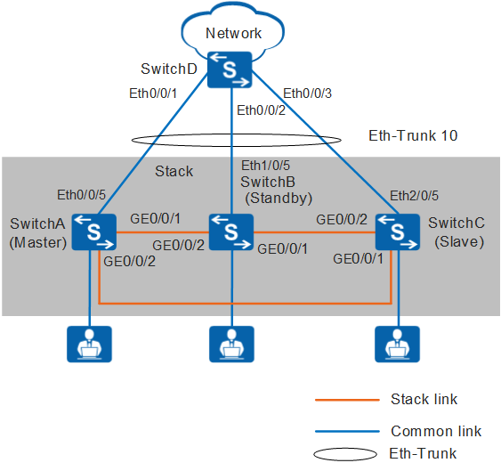
As shown in Figure 1, SwitchA, SwitchB, and SwitchC need to set up a stack in a ring topology and connect to SwitchD through an inter-device Eth-Trunk. SwitchA, SwitchB, and SwitchC are the master, standby, and slave switches respectively, with stack IDs of 0, 1, and 2 and stack priorities of 200, 100, and 100. As the three switches function as one logical device on the network, the number of ports is increased and network management and maintenance are simplified.
In this example, S3700-EIs set up a stack.
Configuration Roadmap
The stacking function is enabled by default on the S3700-EI. Therefore, these switches can set up a stack immediately after they are connected using stack cables, without additional configuration. To facilitate device management and identification, configure device names, stack IDs, and stack priorities for stack member switches.
Power off SwitchA, SwitchB, and SwitchC, connect physical member ports using SFP stack cables, and then power on the three switches.
Configure an inter-device Eth-Trunk to increase reliability and uplink bandwidth.
Procedure
- Configure device names to differentiate devices.
# Configure a device name for SwitchA.
<HUAWEI> system-view
[HUAWEI] sysname SwitchA
# Configure a device name for SwitchB.
<HUAWEI> system-view
[HUAWEI] sysname SwitchB
# Configure a device name for SwitchC.
<HUAWEI> system-view
[HUAWEI] sysname SwitchC
- Configure stack IDs and stack priorities. The default stack ID is 0, and the default stack priority is 100.
[SwitchA] stack slot 0 priority 200 //Set the stack priority of the master switch to 200, which is larger than those of other member switches, and use the default stack ID 0.
[SwitchB] stack slot 0 renumber 1 //Use the default stack priority 100 and set the stack ID to 1.
[SwitchC] stack slot 0 renumber 2 //Use the default stack priority 100 and set the stack ID to 2.
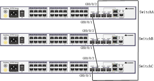
- Turn off power supplies of SwitchA, SwitchB, and SwitchC, connect physical member ports using SFP stack cables as shown in Figure 2, and then power on the three switches.

- Run the save command to save the configurations before you power off the switches.
- To ensure that a stack can be set up successfully, you are advised to perform operations in the following sequence. To specify a member switch as the master switch, power on that switch first. In this example, SwitchA becomes the master switch after you complete the following operations.
- Power off SwitchA, SwitchB, and SwitchC.
- Connect SwitchA and SwitchB with a stack cable.
- Power on and start SwitchA and then power on SwitchB.
- Check whether SwitchA and SwitchB set up a stack successfully. For details, see step 4.
- Connect SwitchC to SwitchB and SwitchA using stack cables and then power on SwitchC.
- Check whether SwitchA, SwitchB, and SwitchC set up a stack successfully. For details, see step 4.
- Check whether a stack is set up successfully.
# Log in to the stack through the console port of the master switch to check whether the number of member switches in the stack is the same as the actual value and whether the stack topology is the same as the actual hardware connection.
<SwitchA> system-view
[SwitchA] sysname Stack
[Stack] display stack
Stack topology type: Ring
Stack system MAC: 0018-82b1-6eb8
MAC switch delay time: never
Stack reserved vlanid : 4093
Slot     Role        Mac address      Priority   Device type
-------------------------------------------------------------
0         Master      0018-82b1-6eb8   200       S3728TP-EI
1         Standby     0018-82c6-1f4c   100       S3728TP-EI
2         Slave       0018-82d2-2e85   100       S3728TP-EI
- Configure an inter-device Eth-Trunk.
# Create an Eth-Trunk in the stack and configure uplink physical ports as Eth-Trunk member ports.
[Stack] interface eth-trunk 10
[Stack-Eth-Trunk10] trunkport ethernet 0/0/5
[Stack-Eth-Trunk10] trunkport ethernet 1/0/5
[Stack-Eth-Trunk10] trunkport ethernet 2/0/5
[Stack-Eth-Trunk10] return
# Create an Eth-Trunk on SwitchD and configure the ports connected to the stack as Eth-Trunk member ports.
<HUAWEI> system-view
[HUAWEI] sysname SwitchD
[SwitchD] interface eth-trunk 10
[SwitchD-Eth-Trunk10] trunkport ethernet 0/0/1
[SwitchD-Eth-Trunk10] trunkport ethernet 0/0/2
[SwitchD-Eth-Trunk10] trunkport ethernet 0/0/3
[SwitchD-Eth-Trunk10] return
- Verify the Eth-Trunk configuration.# Check Eth-Trunk member port information. The following displays information about Eth-Trunk member ports in the stack.
<Stack> display trunkmembership eth-trunk 10
Trunk ID: 10
used status: VALID
TYPE: ethernet
Working Mode : Normal
Number Of Ports in Trunk = 3
Number Of UP Ports in Trunk = 3
operate status: up

Interface Ethernet0/0/5, valid, operate up, weight=1
Interface Ethernet1/0/5, valid, operate up, weight=1
Interface Ethernet2/0/5, valid, operate up, weight=1
Configuration Files
Stack configuration file (the stack configuration is written to the flash memory instead of the configuration file)
#
 sysname Stack
#
interface Eth-Trunk10
#
interface Ethernet0/0/5
 eth-trunk 10
#
interface Ethernet1/0/5
 eth-trunk 10
#
interface Ethernet2/0/5
 eth-trunk 10
#
return
SwitchD configuration file
#
 sysname SwitchD
#
interface Eth-Trunk10
#
interface Ethernet0/0/1
 eth-trunk 10
#
interface Ethernet0/0/2
 eth-trunk 10
#
interface Ethernet0/0/3
 eth-trunk 10
#
return