Example for Establishing a Stack Through Service Port Connections Using Dedicated Stack Cables (V200R011C10 and Later Versions)
Overview
Service port connection allows member switches to be connected using service ports, without requiring dedicated stack cards.
Ordinary cable connection: Switches use optical cables, network cables, and high-speed cables to set up a stack.
Dedicated cable connection: Switches use dedicated stack cables to set up a stack. The two ends of a dedicated stack cable are the master end with the Master tag and the slave end without any tag.
Precautions
- Connect member switches using dedicated stack cables based on the following rules:
- Connect the switches in sequence from top to bottom.
- Ensure that all logical stack ports of the top switch are connected to the master ends of cables, all logical stack ports of the bottom switch are connected to the slave ends of cables, and two logical stack ports of the intermediate switch are connected to the master and slave ends respectively.
- After the switches have been connected using dedicated stack cables, they automatically set up a stack and their stack IDs as well as stack roles are automatically assigned.
- If the switches are not connected in a ring topology, you only need to ensure that logical stack port 1 of the local switch is connected to logical stack port 2 of the remote switch. In this situation, these switches can set up a stack, but their master and standby roles and stack IDs are randomly generated.
- Ensure that there are no service configurations on the ports that have dedicated stack cables connected. Otherwise, these ports cannot automatically become stack ports and the switches cannot set up a stack.
- On ASs in an SVF system, ensure that there are no other configurations except the shutdown and stp root-protection command configurations on ports.
- On switches managed by iMaster NCE-Campus, ensure that there are no other configurations except the shutdown and trust dscp command configurations on ports.
- On other switches, ensure that there are no other configurations except the shutdown command configuration on ports.
- If logical stack port numbers have been manually configured before dedicated stack cables are connected, the configured port numbers still take effect after the cables are connected. You need to connect these ports based on the configured port numbers. If logical stack port numbers are not manually configured, corresponding logical stack port numbers will be automatically generated after dedicated stack cables are connected. To view logical stack ports of ports supporting dedicated stack cables and master as well as slave ends of the cables connected to these ports, run the display stack port auto-cable-info command.
Networking Requirements
An enterprise network needs to provide sufficient ports for access devices, and the network structure should be simple to facilitate configuration and management.
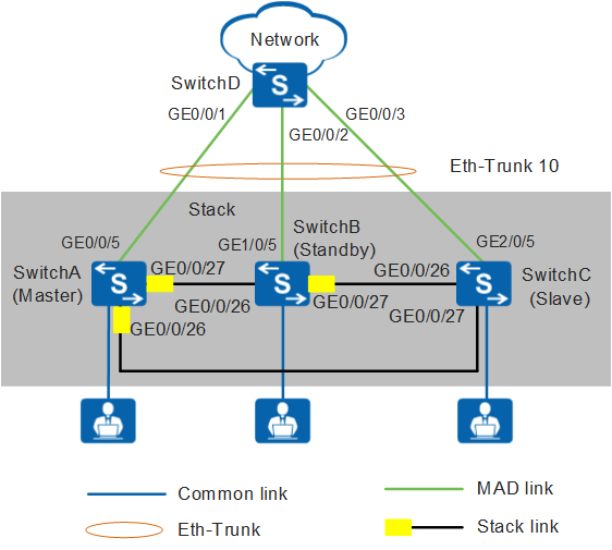
As shown in Figure 1, Switches A to C set up a stack in a ring topology and connect to SwitchD through an inter-chassis Eth-Trunk. To reduce the configuration, Switches A to C set up a stack using dedicated stack cables. In the stack, SwitchA needs to function as the master switch, Switch B as the standby switch, and SwitchC as the slave switch.
This example describes how to use S5720-28P-PWR-LI-AC switches to set up a stack.
Configuration Roadmap
Power off SwitchA, SwitchB, and SwitchC to ensure security.
Connect the switches using dedicated stack cables based on dedicated stack cable connection rules.
Power on these switches in the following sequence to ensure that SwitchA, SwitchB, and SwitchC become the master switch, standby switch, and slave switch respectively.
Save the stack configuration automatically generated for dedicated cable stacking to the flash memory. This ensures that the stack configuration still takes effect when these cables are removed or other cables are connected.
Configure an inter-chassis Eth-Trunk to increase reliability and uplink bandwidth.
Configure multi-active detection in relay mode to ensure network availability when the stack splits.
Procedure
- Power off SwitchA, SwitchB, and SwitchC.
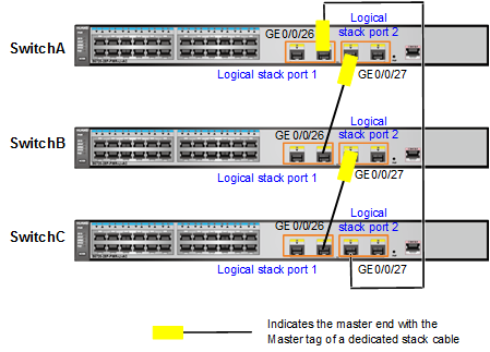
- Power off SwitchA, SwitchB, and SwitchC and then connect them using dedicated stack cables as shown in Figure 2.

- Logical stack port 1 of the local switch must be connected to logical stack port 2 of the adjacent switch. Otherwise, these switches cannot set up a stack.
- All logical stack ports of SwitchA must be connected to the master ends of dedicated stack cables, and all logical stack ports of SwitchC must be connected to the slave ends of these cables.
- Power on SwitchA, SwitchB, and SwitchC in sequence.
# Power on these switches in the following sequence to ensure that SwitchA, SwitchB, and SwitchC become the master switch, standby switch, and slave switch respectively.
- Power on SwitchA first.
- Power on SwitchB after SwitchA starts.
- Power on SwitchC after SwitchB starts.
The preceding power-on sequence can guarantee only roles of these switches but not their slot IDs. The following assumes that SwitchA, SwitchB, and SwitchC use automatically generated slot IDs 0, 1, and 2 respectively.
- Check whether a stack has been set up successfully.
# Check the stack indicator status.
Press the mode switching (MODE) button on any member switch to change the mode status indicator to the stack mode.
- If the mode status indicators on all member switches change to the stack mode, a stack has been set up successfully.
- If the mode status indicator on any member switch does not change to the stack mode, a stack has not been set up.
- The S5700-SI, S5700-EI, S5700-HI, S6700-EI, S5710-C-LI use the same mode status indicator to show the stack and speed modes. After you press the MODE button, the indicator is steady red and off after 45 seconds, indicating that the switch enters the stack mode.
- The S5732-H, S6730-S, S6730S-S, S6720-HI, S6730-H, and S6730S-H have an independent stack master/slave indicator to show the MST. If the indicator is off, the switch is not a stack master. If the indicator is steady green, the switch is a stack master or standalone switch.
- Other models have an independent stack mode indicator (STCK indicator). After you press the MODE button, the indicator is steady green or blinking and off after 45 seconds, indicating that the switch enters the stack mode.
# Check basic stack information.
Log in to the stack through the console port of any member switch to check whether the number of member switches in the stack is the same as the actual value and whether the stack topology status is the same as the actual hardware connection.
<SwitchA> system-view
[SwitchA] sysname Stack
[Stack] display stack
Stack mode: Service-port
Stack topology type : Ring
Stack system MAC: 0018-82d2-2e85
MAC switch delay time: 10 min
Stack reserved vlan : 4093
Slot of the active management port: 0
Slot     Role        Mac address      Priority   Device type
-------------------------------------------------------------
    0     Master      0018-82d2-2e85   100        S5720-28P-LI-AC
    1     Standby     0018-82c6-1f44   100        S5720-28P-LI-AC
    2     Slave       0018-82c6-1f4c   100        S5720-28P-LI-AC
- Save the stack configuration that is automatically generated for dedicated cable stacking to the flash memory.
# After verifying that a stack has been set up, save the stack configuration that is automatically generated for dedicated cable stacking to the flash memory.
[Stack] save stack configuration
Warning: This operation will save all stack configurations to flash. Are you sure you want to continue? [Y/N]:y
- Configure an inter-device Eth-Trunk.
# Create an Eth-Trunk in the stack and configure uplink physical ports as Eth-Trunk member ports.
[Stack] interface eth-trunk 10
[Stack-Eth-Trunk10] trunkport gigabitethernet 0/0/5
[Stack-Eth-Trunk10] trunkport gigabitethernet 1/0/5
[Stack-Eth-Trunk10] trunkport gigabitethernet 2/0/5
[Stack-Eth-Trunk10] quit
# Create an Eth-Trunk on SwitchD and configure the ports connected to the stack as Eth-Trunk member ports.
<HUAWEI> system-view
[HUAWEI] sysname SwitchD
[SwitchD] interface eth-trunk 10
[SwitchD-Eth-Trunk10] trunkport gigabitethernet 0/0/1
[SwitchD-Eth-Trunk10] trunkport gigabitethernet 0/0/2
[SwitchD-Eth-Trunk10] trunkport gigabitethernet 0/0/3
[SwitchD-Eth-Trunk10] quit
- Verify the Eth-Trunk configuration.# Check Eth-Trunk member port information. The following displays information about Eth-Trunk member ports in the stack.
[Stack] display trunkmembership eth-trunk 10
Trunk ID: 10
Used status: VALID
TYPE: ethernet
Working Mode : Normal
Number Of Ports in Trunk = 3
Number Of Up Ports in Trunk = 3
Operate status: up

Interface GigabitEthernet0/0/5, valid, operate up, weight=1
Interface GigabitEthernet1/0/5, valid, operate up, weight=1
Interface GigabitEthernet2/0/5, valid, operate up, weight=1
- Configure MAD in relay mode on SwitchD and configure SwitchD as the relay agent.
# In the stack, configure MAD in relay mode on the inter-chassis Eth-Trunk.
[Stack] interface eth-trunk 10
[Stack-Eth-Trunk10] mad detect mode relay
[Stack-Eth-Trunk10] return
# Configure MAD in relay mode on the relay agent SwitchD.
[SwitchD] interface eth-trunk 10
[SwitchD-Eth-Trunk10] mad relay
[SwitchD-Eth-Trunk10] return
- Verify the MAD configuration.
# Check detailed MAD configuration of the stack.
<Stack> display mad verbose
Current MAD domain: 0
Current MAD status: Detect
Mad direct detect interfaces configured:
Mad relay detect interfaces configured:
 Eth-Trunk10
Excluded ports(configurable):
Excluded ports(can not be configured):
 GigabitEthernet0/0/26
 GigabitEthernet0/0/27
 GigabitEthernet1/0/26
 GigabitEthernet1/0/27
 GigabitEthernet2/0/26
 GigabitEthernet2/0/27
# Check the MAD proxy configuration on SwitchD.
<SwitchD> display mad proxy
Mad relay interfaces configured:
 Eth-Trunk10
Configuration Files
Stack configuration file (the stack configuration is written to the flash memory instead of the configuration file)
#
sysname Stack
#
interface Eth-Trunk10
 mad detect mode relay
#
interface GigabitEthernet0/0/5
 eth-trunk 10
#
interface GigabitEthernet1/0/5
 eth-trunk 10
#
interface GigabitEthernet2/0/5
 eth-trunk 10
#
return
-
#
sysname SwitchD
#
interface Eth-Trunk10
 mad relay
#
interface GigabitEthernet0/0/1
 eth-trunk 10
#
interface GigabitEthernet0/0/2
 eth-trunk 10
#
interface GigabitEthernet0/0/3
 eth-trunk 10
#
return