Example for Configuring SEP and RRPP on a Network
Overview
Generally, redundant links are used to provide link backup and enhance network reliability. The use of redundant links, however, may produce loops. Loops cause infinite looping of packets, leading to broadcast storms and MAC address table instability. As a result, the communication quality deteriorates, and communication services may be interrupted. To block redundant links and ensure that the blocked links can be restored immediately to resume communication when a link fault occurs on a ring network, you can deploy SEP and RRPP on the ring network.
Networking Requirements
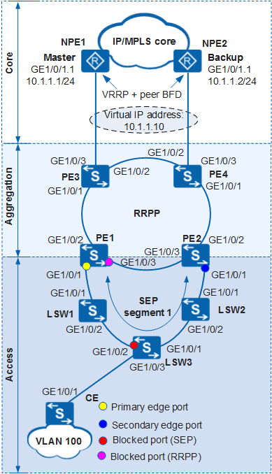
In Figure 1, Layer 2 switching devices at access and aggregation layers constitute a ring network and connect to the core layer. The aggregation layer uses RRPP to eliminate redundant links, and the access layer uses SEP.
- When there is no faulty link on the ring network, SEP can eliminate loops on the Ethernet network.
- When a link fails on the ring network, SEP can quickly restore communication between nodes in the ring.
The topology change notification function is configured on an edge device in a SEP segment so that devices on the upper-layer network can promptly detect topology changes on the lower-layer network.
After receiving a topology change notification from a lower-layer network, a device on an upper-layer network sends a TC packet to instruct other devices to delete original MAC addresses and learn new MAC addresses. This ensures nonstop traffic forwarding.

In this example, NPE1 and NPE2 use NE40Es running V600R008C00.
Configuration Roadmap
The configuration roadmap is as follows:
Configure basic SEP functions.
Configure SEP segment 1 on PE1, PE2, and LSW1 to LSW3 and configure VLAN 10 as the control VLAN of SEP segment 1.
Add PE1, PE2, and LSW1 to LSW3 to SEP segment and configure interface roles on edge devices (PE1 and PE2) of the SEP segment.
On the device where the primary edge interface is located, specify the mode in which an interface is blocked.
Configure a SEP preemption mode to ensure that the specified blocked interface takes effect when the fault is rectified.
Configure the topology change notification function so that the upper-layer network running RRPP can be notified of topology changes in the SEP segment.
Configure basic RRPP functions.
Add PE1 to PE4 to RRPP domain 1, configure VLAN 5 as the control VLAN on PE1 to PE4, and configure the protected VLAN.
Configure PE1 as the master node and PE2 to PE4 as the transit nodes on the major ring, and configure primary and secondary interfaces of the master node.
Create VLANs on PE1 to PE4 and add interfaces on the RRPP ring to the VLANs.
Set up a single-hop BFD session between NPE1 and NPE2 to detect the status of the interfaces configured with VRRP. Then, report the detection result to VRRP to complete VRRP fast switching.
Configure Layer 2 forwarding on the CE, LSW1 to LSW3, and PE1 to PE4.
PEs are aggregation switches, LSWs are access switches, and CEs are user-side switches.
Procedure
- Configure basic SEP functions.
Configure SEP segment 1 and configure VLAN 10 as the control VLAN of SEP segment 1.
# Configure aggregation switch PE1.
<HUAWEI> system-view
[HUAWEI] sysname PE1
[PE1] sep segment 1 //Create SEP segment 1.
[PE1-sep-segment1] control-vlan 10 //Configure VLAN 10 as the control VLAN of SEP segment 1.
[PE1-sep-segment1] protected-instance all //Configure all protected instances of SEP segment 1.
[PE1-sep-segment1] quit
# Configure aggregation switch PE2.
<HUAWEI> system-view
[HUAWEI] sysname PE2
[PE2] sep segment 1 //Create SEP segment 1.
[PE2-sep-segment1] control-vlan 10 //Configure VLAN 10 as the control VLAN of SEP segment 1.
[PE2-sep-segment1] protected-instance all //Configure all protected instances of SEP segment 1.
[PE2-sep-segment1] quit
# Configure access switch LSW1.<HUAWEI> system-view [HUAWEI] sysname LSW1 [LSW1] sep segment 1 //Create SEP segment 1. [LSW1-sep-segment1] control-vlan 10 //Configure VLAN 10 as the control VLAN of SEP segment 1. [LSW1-sep-segment1] protected-instance all //Configure all protected instances of SEP segment 1. [LSW1-sep-segment1] quit
# Configure access switch LSW2.<HUAWEI> system-view [HUAWEI] sysname LSW2 [LSW2] sep segment 1 //Create SEP segment 1. [LSW2-sep-segment1] control-vlan 10 //Configure VLAN 10 as the control VLAN of SEP segment 1. [LSW2-sep-segment1] protected-instance all //Configure all protected instances of SEP segment 1. [LSW2-sep-segment1] quit
# Configure access switch LSW3.<HUAWEI> system-view [HUAWEI] sysname LSW3 [LSW3] sep segment 1 //Create SEP segment 1. [LSW3-sep-segment1] control-vlan 10 //Configure VLAN 10 as the control VLAN of SEP segment 1. [LSW3-sep-segment1] protected-instance all //Configure all protected instances of SEP segment 1. [LSW3-sep-segment1] quit
The control VLAN must be a VLAN that has not been created or used. However, the command for creating a common VLAN is automatically displayed in the configuration file after the control VLAN is created.
Each SEP segment must have a control VLAN. After an interface is added to a SEP segment that has a control VLAN, the interface is automatically added to the control VLAN.
Add aggregation switch PE1, aggregation switch PE2, and access switch LSW1 to LSW3 to SEP segment 1 and configure interface roles.
By default, STP is enabled on Layer 2 interfaces. Before adding an interface to a SEP segment, disable STP on the interface.
# Configure aggregation switch PE1.
[PE1] interface gigabitethernet 1/0/1
[PE1-GigabitEthernet1/0/1] port link-type trunk
[PE1-GigabitEthernet1/0/1] stp disable //Disable STP.
[PE1-GigabitEthernet1/0/1] sep segment 1 edge primary //Configure the interface as the primary edge interface and add it to SEP segment 1.
[PE1-GigabitEthernet1/0/1] quit
# Configure access switch LSW1.
[LSW1] interface gigabitethernet 1/0/1
[LSW1-GigabitEthernet1/0/1] port link-type trunk
[LSW1-GigabitEthernet1/0/1] stp disable //Disable STP.
[LSW1-GigabitEthernet1/0/1] sep segment 1 //Add the interface to SEP segment 1.
[LSW1-GigabitEthernet1/0/1] quit
[LSW1] interface gigabitethernet 1/0/2
[LSW1-GigabitEthernet1/0/2] port link-type trunk
[LSW1-GigabitEthernet1/0/2] stp disable //Disable STP.
[LSW1-GigabitEthernet1/0/2] sep segment 1 //Add the interface to SEP segment 1.
[LSW1-GigabitEthernet1/0/2] quit
# Configure access switch LSW2.
[LSW2] interface gigabitethernet 1/0/1
[LSW2-GigabitEthernet1/0/1] port link-type trunk
[LSW2-GigabitEthernet1/0/1] stp disable //Disable STP.
[LSW2-GigabitEthernet1/0/1] sep segment 1 //Add the interface to SEP segment 1.
[LSW2-GigabitEthernet1/0/1] quit
[LSW2] interface gigabitethernet 1/0/2
[LSW2-GigabitEthernet1/0/2] port link-type trunk
[LSW2-GigabitEthernet1/0/2] stp disable //Disable STP.
[LSW2-GigabitEthernet1/0/2] sep segment 1 //Add the interface to SEP segment 1.
[LSW2-GigabitEthernet1/0/2] quit
# Configure access switch LSW3.
[LSW3] interface gigabitethernet 1/0/1
[LSW3-GigabitEthernet1/0/1] port link-type trunk
[LSW3-GigabitEthernet1/0/1] stp disable //Disable STP.
[LSW3-GigabitEthernet1/0/1] sep segment 1 //Add the interface to SEP segment 1.
[LSW3-GigabitEthernet1/0/1] quit
[LSW3] interface gigabitethernet 1/0/2
[LSW3-GigabitEthernet1/0/2] port link-type trunk
[LSW3-GigabitEthernet1/0/2] stp disable //Disable STP.
[LSW3-GigabitEthernet1/0/2] sep segment 1 //Add the interface to SEP segment 1.
[LSW3-GigabitEthernet1/0/2] quit
# Configure aggregation switch PE2.
[PE2] interface gigabitethernet 1/0/1
[PE2-GigabitEthernet1/0/1] port link-type trunk
[PE2-GigabitEthernet1/0/1] stp disable //Disable STP.
[PE2-GigabitEthernet1/0/1] sep segment 1 edge secondary //Configure the interface as the secondary edge interface and add it to SEP segment 1.
[PE2-GigabitEthernet1/0/1] quit
After the configuration is complete, run the display sep topology command on aggregation switch PE1 to check the topology of the SEP segment. The command output shows that the blocked interface is one of the two interfaces on the link that last completes neighbor negotiation.
[PE1] display sep topology
SEP segment 1
-------------------------------------------------------------------------
System Name          Port Name        Port Role       Port Status     Hop
-------------------------------------------------------------------------
PE1                  GE1/0/1          primary         forwarding      1
LSW1                 GE1/0/1          common          forwarding      2
LSW1                 GE1/0/2          common          forwarding      3
LSW3                 GE1/0/2          common          forwarding      4
LSW3                 GE1/0/1          common          forwarding      5
LSW2                 GE1/0/2          common          forwarding      6
LSW2                 GE1/0/1          common          forwarding      7
PE2                  GE1/0/1          secondary       discarding      8
Specify a blocked interface.
# In SEP segment 1, set the mode of blocking an interface on aggregation switch PE1 where the primary edge interface is located to block the interface in the middle of the SEP segment.
[PE1] sep segment 1
[PE1-sep-segment1] block port middle
Configure a preemption mode.
# In SEP segment 1, configure the manual preemption mode on aggregation switch PE1 where the primary edge interface is located.
[PE1-sep-segment1] preempt manual
Configure the SEP topology change notification function.
Configure devices in SEP segment 1 to notify the RRPP network of topology changes.
# Configure aggregation switch PE1.
[PE1-sep-segment1] tc-notify rrpp
[PE1-sep-segment1] quit
# Configure aggregation switch PE2.
[PE2] sep segment 1
[PE2-sep-segment1] tc-notify rrpp
[PE2-sep-segment1] quit
After the configuration is complete, perform the following operations to verify the configuration. Aggregation switch PE1 is used as an example.
Run the display sep topology command on aggregation switch PE1 to check the topology of the SEP segment.
The command output shows that GE1/0/2 of access switch LSW3 is in discarding state and other interfaces are in forwarding state.
[PE1] display sep topology
SEP segment 1
-------------------------------------------------------------------------
System Name          Port Name        Port Role       Port Status     Hop
-------------------------------------------------------------------------
PE1                  GE1/0/1          primary         forwarding      1
LSW1                 GE1/0/1          common          forwarding      2
LSW1                 GE1/0/2          common          forwarding      3
LSW3                 GE1/0/2          common          discarding      4
LSW3                 GE1/0/1          common          forwarding      5
LSW2                 GE1/0/2          common          forwarding      6
LSW2                 GE1/0/1          common          forwarding      7
PE2                  GE1/0/1          secondary       forwarding      8
Run the display sep interface verbose command on aggregation switch PE1 to check detailed information about interfaces in the SEP segment.
[PE1] display sep interface verbose
SEP segment 1
Control-vlan             :10
Preempt Delay Timer      :0
TC-Notify Propagate to :rrpp
----------------------------------------------------------------
Interface              :GE1/0/1
Port Role              :Config = primary / Active =  primary
Port Priority          :64
Port Status            :forwarding
Neighbor Status        :up
Neighbor Port          :LSW1 - GE1/0/1 (00e0-0829-7c00.0000)
NBR TLV             rx :2124             tx :2126
LSP INFO TLV        rx :2939             tx :135
LSP ACK TLV         rx :113              tx :768
PREEMPT REQ TLV     rx :0                tx :3
PREEMPT ACK TLV     rx :3                tx :0
TC Notify           rx :5                tx :3
EPA                 rx :363              tx :397
- Configure basic RRPP functions.
Add aggregation switch PE1 to PE4 to RRPP domain 1, configure VLAN 5 as the control VLAN on aggregation switch PE1 to PE4, and configure the protected VLAN.
# Configure aggregation switch PE1.
[PE1] stp region-configuration //Enter the MST region view.
[PE1-mst-region] instance 1 vlan 5 6 100 //Map VLAN 5, VLAN 6, and VLAN 100 to MSTI 1.
[PE1-mst-region] active region-configuration //Activate MST region configuration.
[PE1-mst-region] quit
[PE1] rrpp domain 1 //Create RRPP domain 1.
[PE1-rrpp-domain-region1] control-vlan 5 //Configure VLAN 5 as the control VLAN of RRPP domain 1.
[PE1-rrpp-domain-region1] protected-vlan reference-instance 1 //Configure the protected VLAN in protected instance 1.
# Configure aggregation switch PE2.
[PE2] stp region-configuration //Enter the MST region view.
[PE2-mst-region] instance 1 vlan 5 6 100 //Map VLAN 5, VLAN 6, and VLAN 100 to MSTI 1.
[PE2-mst-region] active region-configuration //Activate MST region configuration.
[PE2-mst-region] quit
[PE2] rrpp domain 1 //Create RRPP domain 1.
[PE2-rrpp-domain-region1] control-vlan 5 //Configure VLAN 5 as the control VLAN of RRPP domain 1.
[PE2-rrpp-domain-region1] protected-vlan reference-instance 1 //Configure the protected VLAN in protected instance 1.
# Configure aggregation switch PE3.
[PE3] stp region-configuration //Enter the MST region view.
[PE3-mst-region] instance 1 vlan 5 6 100 //Map VLAN 5, VLAN 6, and VLAN 100 to MSTI 1.
[PE3-mst-region] active region-configuration //Activate MST region configuration.
[PE3-mst-region] quit
[PE3] rrpp domain 1 //Create RRPP domain 1.
[PE3-rrpp-domain-region1] control-vlan 5 //Configure VLAN 5 as the control VLAN of RRPP domain 1.
[PE3-rrpp-domain-region1] protected-vlan reference-instance 1 //Configure the protected VLAN in protected instance 1.
# Configure aggregation switch PE4.
[PE4] stp region-configuration //Enter the MST region view.
[PE4-mst-region] instance 1 vlan 5 6 100 //Map VLAN 5, VLAN 6, and VLAN 100 to MSTI 1.
[PE4-mst-region] active region-configuration //Activate MST region configuration.
[PE4-mst-region] quit
[PE4] rrpp domain 1 //Create RRPP domain 1.
[PE4-rrpp-domain-region1] control-vlan 5 //Configure VLAN 5 as the control VLAN of RRPP domain 1.
[PE4-rrpp-domain-region1] protected-vlan reference-instance 1 //Configure the protected VLAN in protected instance 1.
The control VLAN must be a VLAN that has not been created or used. However, the command for creating a common VLAN is automatically displayed in the configuration file after the control VLAN is created.
Create a VLAN and add interfaces on the ring network to the VLAN.
# On aggregation switch PE1, create VLAN 100 and add GE1/0/1, GE1/0/2, and GE1/0/3 to VLAN 100.
[PE1] vlan 100
[PE1-vlan100] quit
[PE1] interface gigabitethernet 1/0/1
[PE1-GigabitEthernet1/0/1] stp disable //Disable STP.
[PE1-GigabitEthernet1/0/1] port link-type trunk
[PE1-GigabitEthernet1/0/1] port trunk allow-pass vlan 100
[PE1-GigabitEthernet1/0/1] quit
[PE1] interface gigabitethernet 1/0/2
[PE1-GigabitEthernet1/0/2] stp disable //Disable STP.
[PE1-GigabitEthernet1/0/2] port link-type trunk
[PE1-GigabitEthernet1/0/2] port trunk allow-pass vlan 100
[PE1-GigabitEthernet1/0/2] quit
[PE1] interface gigabitethernet 1/0/3
[PE1-GigabitEthernet1/0/3] stp disable //Disable STP.
[PE1-GigabitEthernet1/0/3] port link-type trunk
[PE1-GigabitEthernet1/0/3] port trunk allow-pass vlan 100
[PE1-GigabitEthernet1/0/3] quit
# On aggregation switch PE2, create VLAN 100 and add GE1/0/1, GE1/0/2, and GE1/0/3 to VLAN 100.
[PE2] vlan 100
[PE2-vlan100] quit
[PE2] interface gigabitethernet 1/0/1
[PE2-GigabitEthernet1/0/1] stp disable //Disable STP.
[PE2-GigabitEthernet1/0/1] port link-type trunk
[PE2-GigabitEthernet1/0/1] port trunk allow-pass vlan 100
[PE2-GigabitEthernet1/0/1] quit
[PE2] interface gigabitethernet 1/0/2
[PE2-GigabitEthernet1/0/2] stp disable //Disable STP.
[PE2-GigabitEthernet1/0/2] port link-type trunk
[PE2-GigabitEthernet1/0/2] port trunk allow-pass vlan 100
[PE2-GigabitEthernet1/0/2] quit
[PE2] interface gigabitethernet 1/0/3
[PE2-GigabitEthernet1/0/3] stp disable //Disable STP.
[PE2-GigabitEthernet1/0/3] port link-type trunk
[PE2-GigabitEthernet1/0/3] port trunk allow-pass vlan 100
[PE2-GigabitEthernet1/0/3] quit
# On aggregation switch PE3, create VLAN 100 and add GE1/0/1 and GE1/0/2 to VLAN 100.
[PE3] vlan 100
[PE3-vlan100] quit
[PE3] interface gigabitethernet 1/0/1
[PE3-GigabitEthernet1/0/1] stp disable //Disable STP.
[PE3-GigabitEthernet1/0/1] port link-type trunk
[PE3-GigabitEthernet1/0/1] port trunk allow-pass vlan 100
[PE3-GigabitEthernet1/0/1] quit
[PE3] interface gigabitethernet 1/0/2
[PE3-GigabitEthernet1/0/2] stp disable //Disable STP.
[PE3-GigabitEthernet1/0/2] port link-type trunk
[PE3-GigabitEthernet1/0/2] port trunk allow-pass vlan 100
[PE3-GigabitEthernet1/0/2] quit
# On aggregation switch PE4, create VLAN 100 and add GE1/0/1 and GE1/0/2 to VLAN 100.
[PE4] vlan 100
[PE4-vlan100] quit
[PE4] interface gigabitethernet 1/0/1
[PE4-GigabitEthernet1/0/1] stp disable //Disable STP.
[PE4-GigabitEthernet1/0/1] port link-type trunk
[PE4-GigabitEthernet1/0/1] port trunk allow-pass vlan 100
[PE4-GigabitEthernet1/0/1] quit
[PE4] interface gigabitethernet 1/0/2
[PE4-GigabitEthernet1/0/2] stp disable //Disable STP.
[PE4-GigabitEthernet1/0/2] port link-type trunk
[PE4-GigabitEthernet1/0/2] port trunk allow-pass vlan 100
[PE4-GigabitEthernet1/0/2] quit
Configure aggregation switch PE1 as the master node and aggregation switch PE2 to PE4 as the transit nodes on the major ring, and configure primary and secondary interfaces of the master node.
# Configure aggregation switch PE1.
[PE1] rrpp domain 1 //Enter the view of RRPP domain 1.
[PE1-rrpp-domain-region1] ring 1 node-mode master primary-port gigabitethernet 1/0/2 secondary-port gigabitethernet 1/0/3 level 0 //Configure the master node on RRPP primary ring 1 in RRPP domain 1, and configure GE1/0/2 as the primary interface and GE1/0/3 as the secondary interface.
[PE1-rrpp-domain-region1] ring 1 enable //Enable the RRPP ring.
# Configure aggregation switch PE2.
[PE2] rrpp domain 1 //Enter the view of RRPP domain 1.
[PE2-rrpp-domain-region1] ring 1 node-mode transit primary-port gigabitethernet 1/0/2 secondary-port gigabitethernet 1/0/3 level 0 //Configure the transit node on RRPP primary ring 1 in RRPP domain 1, and configure GE1/0/2 as the primary interface and GE1/0/3 as the secondary interface.
[PE2-rrpp-domain-region1] ring 1 enable //Enable the RRPP ring.
# Configure aggregation switch PE3.
[PE3] rrpp domain 1 //Enter the view of RRPP domain 1.
[PE3-rrpp-domain-region1] ring 1 node-mode transit primary-port gigabitethernet 1/0/1 secondary-port gigabitethernet 1/0/2 level 0 //Configure the transit node on RRPP primary ring 1 in RRPP domain 1, and configure GE1/0/1 as the primary interface and GE1/0/2 as the secondary interface.
[PE3-rrpp-domain-region1] ring 1 enable //Enable the RRPP ring.
# Configure aggregation switch PE4.
[PE4] rrpp domain 1 //Enter the view of RRPP domain 1.
[PE4-rrpp-domain-region1] ring 1 node-mode transit primary-port gigabitethernet1/0/1 secondary-port gigabitethernet1/0/2 level 0 //Configure the transit node on RRPP primary ring 1 in RRPP domain 1, and configure GE1/0/1 as the primary interface and GE1/0/2 as the secondary interface.
[PE4-rrpp-domain-region1] ring 1 enable //Enable the RRPP ring.
Enable RRPP.
# Configure aggregation switch PE1.
[PE1] rrpp enable
# Configure aggregation switch PE2.
[PE2] rrpp enable
# Configure aggregation switch PE3.
[PE3] rrpp enable
# Configure aggregation switch PE4.
[PE4] rrpp enable
After the configuration is complete, run the display rrpp brief or display rrpp verbose domain command. Aggregation switch PE1 is used as an example.[PE1] display rrpp brief Abbreviations for Switch Node Mode : M - Master , T - Transit , E - Edge , A - Assistant-Edge RRPP Protocol Status: Enable RRPP Working Mode: HW RRPP Linkup Delay Timer: 0 sec (0 sec default) Number of RRPP Domains: 1 Domain Index : 1 Control VLAN : major 5 sub 6 Protected VLAN : Reference Instance 1 Hello Timer : 1 sec(default is 1 sec) Fail Timer : 6 sec(default is 6 sec) Ring Ring Node Primary/Common Secondary/Edge Is ID Level Mode Port Port Enabled ---------------------------------------------------------------------------- 1 0 M GigabitEthernet1/0/2 GigabitEthernet1/0/3 YesAccording to the preceding information, RRPP is enabled on aggregation switch PE1. The major control VLAN is VLAN 5 and the sub-control VLAN is VLAN 6 in RRPP domain 1. VLANs mapping Instance1 are protected VLANs. Aggregation switch PE1 is the master node in ring 1. The primary interface is GE1/0/2 and the secondary interface is GE1/0/3.
[PE1] display rrpp verbose domain 1
Domain Index   : 1
Control VLAN   : major 5    sub 6
Protected VLAN : Reference Instance 1
Hello Timer    : 1 sec(default is 1 sec)  Fail Timer : 6 sec(default is 6 sec)
RRPP Ring      : 1
Ring Level     : 0
Node Mode      : Master
Ring State     : Complete
Is Enabled     : Enable                             Is Active: Yes
Primary port   : GigabitEthernet1/0/2               Port status: UP
Secondary port : GigabitEthernet1/0/3               Port status: BLOCKED
The major control VLAN is VLAN 5 and the sub-control VLAN is VLAN 6 in RRPP domain 1. VLANs mapping Instance1 are protected VLANs. Aggregation switch PE1 is the master node in Complete state. The primary interface is GE1/0/2 and the secondary interface is GE1/0/3.
- Configure VLAN 100 to transmit VRRP packets and VLAN 200 to transmit BFD packets.
# Configure aggregation switch PE3.
[PE3] vlan batch 100 200
[PE3] interface gigabitethernet 1/0/2
[PE3-GigabitEthernet1/0/2] stp disable //Disable STP.
[PE3-GigabitEthernet1/0/2] port link-type trunk
[PE3-GigabitEthernet1/0/2] port trunk allow-pass vlan 100 200
[PE3-GigabitEthernet1/0/2] quit
[PE3] interface gigabitethernet 1/0/3
[PE3-GigabitEthernet1/0/3] stp disable //Disable STP.
[PE3-GigabitEthernet1/0/3] port link-type trunk
[PE3-GigabitEthernet1/0/3] port trunk allow-pass vlan 100 200
[PE3-GigabitEthernet1/0/3] quit
# Configure aggregation switch PE4.
[PE4] vlan batch 100 200
[PE4] interface gigabitethernet 1/0/2
[PE4-GigabitEthernet1/0/2] stp disable //Disable STP.
[PE4-GigabitEthernet1/0/2] port link-type trunk
[PE4-GigabitEthernet1/0/2] port trunk allow-pass vlan 100 200
[PE4-GigabitEthernet1/0/2] quit
[PE4] interface gigabitethernet 1/0/3
[PE4-GigabitEthernet1/0/3] stp disable //Disable STP.
[PE4-GigabitEthernet1/0/3] port link-type trunk
[PE4-GigabitEthernet1/0/3] port trunk allow-pass vlan 100 200
[PE4-GigabitEthernet1/0/3] quit
- Configure a BFD session.
Configure IP addresses for interfaces.
# Configure an IP address for an interface on NPE1 and create a sub-interface for the interface.
<HUAWEI> system-view
[HUAWEI] sysname NPE1
[NPE1] vlan 100
[NPE1-vlan100] quit
[NPE1] interface gigabitethernet 1/0/1
[NPE1-GigabitEthernet1/0/1] undo shutdown
[NPE1-GigabitEthernet1/0/1] ip address 10.2.1.1 24
[NPE1-GigabitEthernet1/0/1] quit
[NPE1] interface gigabitethernet 1/0/1.1
[NPE1-GigabitEthernet1/0/1.1] undo shutdown
[NPE1-GigabitEthernet1/0/1.1] vlan-type dot1q 100
[NPE1-GigabitEthernet1/0/1.1] ip address 10.1.1.1 24
[NPE1-GigabitEthernet1/0/1.1] quit
# Configure an IP address for an interface on NPE2 and create a sub-interface for the interface.
<HUAWEI> system-view
[HUAWEI] sysname NPE2
[NPE2] vlan 100
[NPE2-vlan100] quit
[NPE2] interface gigabitethernet 1/0/1
[NPE2-GigabitEthernet1/0/1] undo shutdown
[NPE2-GigabitEthernet1/0/1] ip address 10.2.1.2 24
[NPE2-GigabitEthernet1/0/1] quit
[NPE2] interface gigabitethernet 1/0/1.1
[NPE2-GigabitEthernet1/0/1.1] undo shutdown
[NPE2-GigabitEthernet1/0/1.1] vlan-type dot1q 100
[NPE2-GigabitEthernet1/0/1.1] ip address 10.1.1.2 24
[NPE2-GigabitEthernet1/0/1.1] quit
-
# Enable BFD on NPE1 and configure a BFD session between NPE1 and NPE2.
[NPE1] bfd
[NPE1-bfd] quit
[NPE1] bfd NPE2 bind peer-ip default-ip interface gigabitethernet 1/0/1 //Configure a static BFD session to monitor the link of the VRRP group.
[NPE1-bfd-session-npe2] discriminator local 1
[NPE1-bfd-session-npe2] discriminator remote 2
[NPE1-bfd-session-npe2] commit
[NPE1-bfd-session-npe2] quit
# Enable BFD on NPE2 and configure a BFD session between NPE1 and NPE2.
[NPE2] bfd
[NPE2-bfd] quit
[NPE2] bfd NPE1 bind peer-ip default-ip interface gigabitethernet 1/0/1 //Configure a static BFD session to monitor the link of the VRRP group.
[NPE2-bfd-session-npe1] discriminator local 2
[NPE2-bfd-session-npe1] discriminator remote 1
[NPE2-bfd-session-npe1] commit
[NPE2-bfd-session-npe1] quit
# After completing the configuration, run the display bfd session all on NPE1 and NPE2. The command output shows that the BFD session is set up between NPE1 and NPE2 and its status is Up.
Use the display on NPE1 as an example.
[NPE1] display bfd session all
--------------------------------------------------------------------------------
Local Remote PeerIpAddr      State     Type        InterfaceName
--------------------------------------------------------------------------------
1     2      224.0.0.184     Up        S_IP_IF     GigabitEthernet1/0/1
--------------------------------------------------------------------------------
     Total UP/DOWN Session Number : 1/0
Configure association between BFD status and sub-interface status.
# Configure NPE1.
[NPE1] bfd
[NPE1-bfd] quit
[NPE1] bfd NPE2
[NPE1-bfd-session-npe2] process-interface-status sub-if
[NPE1-bfd-session-npe2] commit
[NPE1-bfd-session-npe2] quit
# Configure NPE2.
[NPE2] bfd
[NPE2-bfd] quit
[NPE2] bfd NPE1
[NPE2-bfd-session-npe1] process-interface-status sub-if
[NPE2-bfd-session-npe1] commit
[NPE2-bfd-session-npe1] quit
After completing the preceding configurations, run the display bfd session all verbose command on NPE1 and NPE2. Check that the Proc interface status field displays Enable (Sub-If).
Use the display on NPE1 as an example.
[NPE1] display bfd session all verbose
--------------------------------------------------------------------------------
Session MIndex : 257       (One Hop) State : Up        Name : npe2
--------------------------------------------------------------------------------
  Local Discriminator    : 1                Remote Discriminator   : 2
  Session Detect Mode    : Asynchronous Mode Without Echo Function
  BFD Bind Type          : Interface(GigabitEthernet1/0/1)
  Bind Session Type      : Static
  Bind Peer IP Address   : 224.0.0.184
  NextHop Ip Address     : 224.0.0.184
  Bind Interface         : GigabitEthernet1/0/1
  FSM Board Id           : 0                TOS-EXP                : 7
  Min Tx Interval (ms)   : 1000             Min Rx Interval (ms)   : 1000
  Actual Tx Interval (ms): 1000             Actual Rx Interval (ms): 1000
  Local Detect Multi     : 3                Detect Interval (ms)   : 3000
  Echo Passive           : Disable          Acl Number             : -
  Destination Port       : 3784             TTL                    : 255
  Proc Interface Status  : Enable(Sub-If)   Process PST            : Disable
  WTR Interval (ms)      : -                Local Demand Mode      : Disable
  Active Multi           : 3
  Last Local Diagnostic  : No Diagnostic
  Bind Application       : IFNET
  Session TX TmrID       : 93               Session Detect TmrID   : 94
  Session Init TmrID     : -                Session WTR TmrID      : -
  Session Echo Tx TmrID  : -
  PDT Index              : FSM-0 | RCV-0 | IF-0 | TOKEN-0
  Session Description    : -
--------------------------------------------------------------------------------

     Total UP/DOWN Session Number : 1/0
- Configure VRRP.
# Configure an IP address for an interface on NPE1, create VRRP group 1, and set the VRRP priority of NPE1 to 120 so that NPE1 can function as the master.
[NPE1] interface gigabitethernet 1/0/1.1
[NPE1-GigabitEthernet1/0/1.1] vrrp vrid 1 virtual-ip 10.1.1.10
[NPE1-GigabitEthernet1/0/1.1] vrrp vrid 1 priority 120 //The default priority of a device in a VRRP group is 100. Change the priority of the master to be higher than that of the backup.
[NPE1-GigabitEthernet1/0/1.1] vrrp vrid 1 preempt-mode timer delay 10 //A device in a VRRP group uses immediate preemption by default. Change the preemption delay of the master to prevent service interruptions on an unstable network where devices in the VRRP group preempt to be the master.
# Configure an IP address for an interface on NPE2, create VRRP group 1, and allow NPE2 to use the default value so that NPE1 can function as the backup.
[NPE2] interface gigabitethernet 1/0/1.1
[NPE2-GigabitEthernet1/0/1.1] vrrp vrid 1 virtual-ip 10.1.1.10
# On NPE1, bind the VRRP group and the BFD session.
[NPE1-GigabitEthernet1/0/1.1] vrrp vrid 1 track bfd-session 1 peer
[NPE1-GigabitEthernet1/0/1.1] quit
# On NPE2, bind the VRRP group and the BFD session.
[NPE2-GigabitEthernet1/0/1.1] vrrp vrid 1 track bfd-session 2 peer
[NPE2-GigabitEthernet1/0/1.1] quit
After completing the preceding configurations, run the display vrrp command on NPE1. Check that the status of NPE1 is Master. Run the display vrrp command on NPE2. Check that the status of NPE2 is Backup.[NPE1] display vrrp GigabitEthernet1/0/1.1 | Virtual Router 1 State : Master Virtual IP : 10.1.1.10 Master IP : 10.1.1.1 PriorityRun : 120 PriorityConfig : 120 MasterPriority : 120 Preempt : YES Delay Time : 10 TimerRun : 1 TimerConfig : 1 Auth Type : NONE Virtual Mac : 0000-5e00-0101 Check TTL : YES Config type : normal-vrrp Backup-forward : disabled Config track link-bfd down-number : 0 Track BFD : 1 type: peer BFD-session state : UP Create time : 2013-12-29 22:46:32 UTC+07:00 Last change time : 2013-12-29 22:46:35 UTC+07:00[NPE2] display vrrp GigabitEthernet1/0/1.1 | Virtual Router 1 State : Backup Virtual IP : 10.1.1.10 Master IP : 10.1.1.2 PriorityRun : 100 PriorityConfig : 100 MasterPriority : 120 Preempt : YES Delay Time : 0 TimerRun : 1 TimerConfig : 1 Auth Type : NONE Virtual Mac : 0000-5e00-0101 Check TTL : YES Config type : normal-vrrp Backup-forward : disabled Config track link-bfd down-number : 0 Track BFD : 2 type: peer BFD-session state : UP Create time : 2013-12-29 22:46:32 UTC+07:00 Last change time : 2013-12-29 22:46:35 UTC+07:00 - Configure Layer 2 forwarding on the user-side switch CE, access switch LSW1 to LSW3, and aggregation switch PE1 to PE4.
The configuration details are not mentioned here. For details, see configuration files in this example.
- Verify the configuration.
After the configuration is complete and the network topology becomes stable, perform the following operations to verify the configuration.
# Run the shutdown command on GE1/0/1 of LSW2 to simulate a fault, and then run the display sep interface command on LSW3 to check whether GE1/0/2 on LSW3 changes from the discarding state to the forwarding state.
[LSW3] display sep interface gigabitethernet 1/0/2
SEP segment 1
----------------------------------------------------------------
Interface           Port Role     Neighbor Status     Port Status
----------------------------------------------------------------
GE1/0/2             common        up                  forwarding
Run the shutdown command on GE 1/0/1.1 on NPE1 to simulate an interface fault, and then run the display vrrp command on NPE2 to check whether the status of NPE2 changes from backup to master.
[NPE2] display vrrp
GigabitEthernet1/0/1.1 | Virtual Router 1
    State : Master
    Virtual IP : 10.1.1.10
    Master IP      : 10.1.1.2
    PriorityRun : 100
    PriorityConfig : 100
     MasterPriority : 100
    Preempt : YES   Delay Time : 0
    TimerRun : 1
    TimerConfig : 1
    Auth Type : NONE
    Virtual Mac :  0000-5e00-0101
    Check TTL : YES
    Config type : normal-vrrp
    Backup-forward : disabled
    Config track link-bfd down-number : 0
    Track BFD : 2  type: peer
    BFD-session state : DOWN
    Create time : 2013-12-29 22:46:32 UTC+07:00
    Last change time : 2013-12-30 00:12:10 UTC+07:00
Configuration Files
LSW1 configuration file
#
sysname LSW1
#
vlan batch 10 100
#
sep segment 1
 control-vlan 10
 protected-instance 0 to 4094
#
interface GigabitEthernet1/0/1
 port link-type trunk
 port trunk allow-pass vlan 10 100
 stp disable
 sep segment 1
#
interface GigabitEthernet1/0/2
 port link-type trunk
 port trunk allow-pass vlan 10 100
 stp disable
 sep segment 1
#
return
LSW2 configuration file
#
sysname LSW2
#
vlan batch 10 100
#
sep segment 1
 control-vlan 10
 protected-instance 0 to 4094
#
interface GigabitEthernet1/0/1
 port link-type trunk
 port trunk allow-pass vlan 10 100
 stp disable
 sep segment 1
#
interface GigabitEthernet1/0/2
 port link-type trunk
 port trunk allow-pass vlan 10 100
 stp disable
 sep segment 1
#
return
LSW3 configuration file
#
sysname LSW3
#
vlan batch 10 100
#
sep segment 1
 control-vlan 10
 protected-instance 0 to 4094
#
interface GigabitEthernet1/0/1
 port link-type trunk
 port trunk allow-pass vlan 10 100
 stp disable
 sep segment 1
#
interface GigabitEthernet1/0/2
 port link-type trunk
 port trunk allow-pass vlan 10 100
 stp disable
 sep segment 1
#
interface GigabitEthernet1/0/3
 port link-type trunk
 port trunk allow-pass vlan 100
#
return
PE1 configuration file
#
sysname PE1
#
vlan batch 5 to 6 10 100
#
rrpp enable
#
stp region-configuration
 instance 1 vlan 5 to 6 100
 active region-configuration
#
rrpp domain 1
 control-vlan 5
 protected-vlan reference-instance 1
 ring 1 node-mode master primary-port GigabitEthernet 1/0/2 secondary-port GigabitEthernet 1/0/3 level 0
 ring 1 enable
#
sep segment 1
 control-vlan 10
 block port middle
 tc-notify rrpp
 protected-instance 0 to 4094
#
interface GigabitEthernet1/0/1
 port link-type trunk
 port trunk allow-pass vlan 10 100
 stp disable
 sep segment 1 edge primary
#
interface GigabitEthernet1/0/2
 port link-type trunk
 port trunk allow-pass vlan 5 to 6 100
 stp disable
#
interface GigabitEthernet1/0/3
 port link-type trunk
 port trunk allow-pass vlan 5 to 6 100
 stp disable
#
return
PE2 configuration file
#
sysname PE2
#
vlan batch 5 to 6 10 100
#
rrpp enable
#
stp region-configuration
 instance 1 vlan 5 to 6 100
 active region-configuration
#
rrpp domain 1
 control-vlan 5
 protected-vlan reference-instance 1
 ring 1 node-mode transit primary-port GigabitEthernet 1/0/2 secondary-port GigabitEthernet 1/0/3 level 0
 ring 1 enable
#
sep segment 1
 control-vlan 10
 tc-notify rrpp
 protected-instance 0 to 4094
#
interface GigabitEthernet1/0/1
 port link-type trunk
 port trunk allow-pass vlan 10 100
 stp disable
 sep segment 1 edge secondary
#
interface GigabitEthernet1/0/2
 port link-type trunk
 port trunk allow-pass vlan 5 to 6 100
 stp disable
#
interface GigabitEthernet1/0/3
 port link-type trunk
 port trunk allow-pass vlan 5 to 6 100
 stp disable
#
return
PE3 configuration file
#
sysname PE3
#
vlan batch 5 to 6 100 200
#
rrpp enable
#
stp region-configuration
 instance 1 vlan 5 to 6 100
 active region-configuration
#
rrpp domain 1
 control-vlan 5
 protected-vlan reference-instance 1
 ring 1 node-mode transit primary-port GigabitEthernet 1/0/1 secondary-port GigabitEthernet 1/0/2 level 0
 ring 1 enable
#
interface GigabitEthernet1/0/1
 port link-type trunk
 port trunk allow-pass vlan 100
 stp disable
#
interface GigabitEthernet1/0/2
 port link-type trunk
 port trunk allow-pass vlan 5 to 6 100 200
 stp disable
#
interface GigabitEthernet1/0/3
 port link-type trunk
 port trunk allow-pass 100 200
 stp disable
#
return
PE4 configuration file
#
sysname PE4
#
vlan batch 5 to 6 100 200
#
rrpp enable
#
stp region-configuration
 instance 1 vlan 5 to 6 100
 active region-configuration
#
rrpp domain 1
 control-vlan 5
 protected-vlan reference-instance 1
 ring 1 node-mode transit primary-port GigabitEthernet 1/0/1 secondary-port GigabitEthernet 1/0/2 level 0
 ring 1 enable
#
interface GigabitEthernet1/0/1
 port link-type trunk
 port trunk allow-pass vlan 100
 stp disable
#
interface GigabitEthernet1/0/2
 port link-type trunk
 port trunk allow-pass vlan 5 to 6 100 200
 stp disable
#
interface GigabitEthernet1/0/3
 port link-type trunk
 port trunk allow-pass 100 200
 stp disable
#
return
-
#
 sysname NPE1
#
 vlan batch 100
#
 bfd
#
interface GigabitEthernet1/0/1
 undo shutdown
 ip address 10.2.1.1 255.255.255.0
#
interface GigabitEthernet1/0/1.1
 vlan-type dot1q 100
 ip address 10.1.1.1 255.255.255.0
 vrrp vrid 1 virtual-ip 10.1.1.10
 vrrp vrid 1 priority 120
 vrrp vrid 1 preempt-mode timer delay 10
 vrrp vrid 1 track bfd-session 1 peer
#
bfd npe2 bind peer-ip default-ip interface GigabitEthernet1/0/1
 discriminator local 1
 discriminator remote 2
 process-interface-status sub-if
 commit
#
return
-
#
 sysname NPE2
#
 vlan batch 100
#
 bfd
#
interface GigabitEthernet1/0/1
 undo shutdown
 ip address 10.2.1.2 255.255.255.0
#
interface GigabitEthernet1/0/1.1
 vlan-type dot1q 100
 ip address 10.1.1.2 255.255.255.0
 vrrp vrid 1 virtual-ip 10.1.1.10
 vrrp vrid 1 track bfd-session 2 peer
#
bfd npe1 bind peer-ip default-ip interface GigabitEthernet1/0/1
 discriminator local 2
 discriminator remote 1
 process-interface-status sub-if
 commit
#
return
CE configuration file
#
sysname CE1
#
vlan batch 100
#
interface GigabitEthernet1/0/1
 port link-type trunk
 port trunk allow-pass vlan 100
#
return