Example for Configuring VBST
Overview
VLAN-based Spanning Tree (VBST) constructs a spanning tree in each VLAN so that traffic from different VLANs can be forwarded through different spanning trees. VBST is a Huawei proprietary that is equivalent to the Spanning Tree Protocol (STP) or Rapid Spanning Tree Protocol (RSTP) running in each VLAN. Spanning trees in different VLANs are independent of each other.
Currently, the three standard spanning tree protocols are STP, RSTP, and Multiple Spanning Tree Protocol (MSTP). STP and RSTP cannot implement VLAN-based load balancing, because all the VLANs on a LAN share a spanning tree and packets in all VLANs are forwarded along this spanning tree. In addition, the blocked link does not carry any traffic, which wastes bandwidth and may prevent some VLANs from forwarding packets. MSTP is generally preferred because it is compatible with STP and RSTP, ensures fast convergence, and provides multiple paths to load balance traffic.
On enterprise networks, enterprise users need functions that are easy to use and maintain, whereas the configuration of MSTP multi-instance and multi-process is complex and requires in-depth knowledge.
To address this issue, Huawei developed VBST. VBST constructs a spanning tree in each VLAN so that traffic from different VLANs is load balanced along different spanning trees. In addition, VBST is easy to configure and maintain.
Configuration Notes
This example applies to all models of V200R005C00 and later versions.
When HVRP is enabled on a modular switch, do not change the STP mode to VBST.
When VBST is enabled on a ring network, VBST immediately starts spanning tree calculation. Parameters such as the device priority and port priority affect spanning tree calculation, and changes of these parameters may cause network flapping. To ensure fast and stable spanning tree calculation, perform basic configurations on the switch and interfaces before enabling VBST.
If the protected instance has been configured in a SEP segment or ERPS ring but the mapping between protected instances and VLANs is not configured, VBST cannot be enabled.
VBST cannot be enabled in the ignored VLAN or control VLAN used by ERPS, RRPP, SEP, or Smart Link.
- If 1:N (N>1) mapping between MSTIs and VLANs has been configured on the switch, you must delete the mapping before changing the STP working mode to VBST.
- If stp vpls-subinterface enable has been configured on the switch, you must run the undo stp vpls-subinterface enable command on the interface before changing the STP working mode to VBST.
If the device has been configured as the root bridge or secondary root bridge, run the undo stp vlan { vlan-id1 [ to vlan-id2 ] } &<1-10> root command to disable the root bridge or secondary root bridge function and run the stp vlan { vlan-id1 [ to vlan-id2 ] } &<1-10> priority priority command to change the device priority.
When the number of MSTIs that are dynamically specified exceeds the number of protected VLANs, STP is disabled in a created VLAN in the configuration file, for example, stp vlan 100 disable.
To prevent frequent network flapping, ensure that the values of Hello time, Forward Delay, and Max Age conform to the following formulas:
2 x (Forward Delay - 1.0 second) >= Max Age
Max Age >= 2 x (Hello Time + 1.0 second)
It is recommended that fast convergence in normal mode be used. If the fast mode is used, frequently deleting ARP entries may result in 100% CPU usage of the Switch. As a result, packet processing expires and network flapping occurs.
After all ports are configured as edge ports and BPDU filter ports in the system view, none of ports on the switch send BPDUs or negotiate the VBST status with directly connected ports on the peer device. All ports are in forwarding state. This may cause loops on the network, leading to broadcast storms. Exercise caution when you configure a port as an edge port and BPDU filter port.
After a port is configured as an edge port and BPDU filter port in the interface view, the port does not process or send BPDUs. The port cannot negotiate the VBST status with the directly connected port on the peer device. Exercise caution when you configure a port as an edge port and BPDU filter port.
Root protection takes effect only on designated ports.
An alternate port is the backup of the root port. If a switch has an alternate port, configure loop protection on both the root port and alternate port.
Networking Requirements
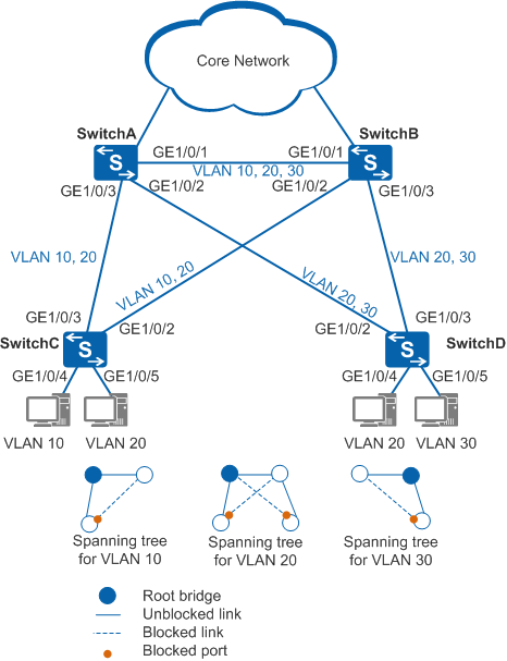
In Figure 1, SwitchC and SwitchD (access switches) are dual-homed to SwitchA and SwitchB (aggregation switches). SwitchC transmits traffic from VLAN 10 and VLAN 20, and SwitchD transmits traffic from VLAN 20 and VLAN 30. A ring network is formed between the access layer and aggregation layer. The enterprise requires that service traffic in each VLAN be correctly forwarded and service traffic from different VLANs be load balanced to improve link use efficiency.
Configuration Roadmap
VBST can be used to eliminate loops between the access layer and aggregation layer and ensures that service traffic in each VLAN is correctly forwarded. In addition, traffic from different VLANs can be load balanced. The configuration roadmap is as follows:
- Configure Layer 2 forwarding on access and aggregation switches.
Configure basic VBST functions on SwitchA, SwitchB, SwitchC, and SwitchD. Perform the following operations so that a spanning tree shown in Figure 1 is formed through calculation:
- Configure SwitchA and SwitchB as the root bridge and secondary root bridge of VLAN 10 respectively, configure SwitchA and SwitchB as the root bridge and secondary root bridge of VLAN 20 respectively, and configure SwitchB and SwitchA as the root bridge and secondary root bridge of VLAN 30 respectively.
- Set a larger path cost for GE1/0/2 on SwitchC in VLAN 10 and VLAN 20 so that GE1/0/2 is blocked in spanning trees of VLAN 10 and VLAN 20. Set a larger path cost for GE1/0/2 on SwitchD in VLAN 20 and VLAN 30 so that GE1/0/2 is blocked in the spanning tree of VLAN 20 and VLAN 30.
- Configure ports on SwitchC and SwitchD connected to terminals as edge ports to reduce VBST topology calculation and improve topology convergence.
Procedure
- Configure Layer 2 forwarding on switches of the ring network.
Create VLAN 10, VLAN 20, and VLAN 30 on SwitchA, SwitchB, SwitchC, and SwitchD.
# Create VLAN 10, VLAN 20, and VLAN 30 on aggregation switch SwitchA.
<HUAWEI> system-view
[HUAWEI] sysname SwitchA
[SwitchA] vlan batch 10 20 30
# Create VLAN 10, VLAN 20, and VLAN 30 on aggregation switch SwitchB.
<HUAWEI> system-view
[HUAWEI] sysname SwitchB
[SwitchB] vlan batch 10 20 30
# Create VLAN 10 and VLAN 20 on access switch SwitchC.
<HUAWEI> system-view
[HUAWEI] sysname SwitchC
[SwitchC] vlan batch 10 20
# Create VLAN 20 and VLAN 30 on access switch SwitchD.
<HUAWEI> system-view
[HUAWEI] sysname SwitchD
[SwitchD] vlan batch 20 30
Add ports connected to the ring to VLANs.
# Add GE1/0/1 on SwitchA to VLAN 10, VLAN 20, and VLAN 30.
[SwitchA] interface gigabitethernet 1/0/1
[SwitchA-GigabitEthernet1/0/1] port link-type trunk
[SwitchA-GigabitEthernet1/0/1] port trunk allow-pass vlan 10 20 30
[SwitchA-GigabitEthernet1/0/1] quit
# Add GE1/0/2 on SwitchA to VLAN 20 and VLAN 30.
[SwitchA] interface gigabitethernet 1/0/2
[SwitchA-GigabitEthernet1/0/2] port link-type trunk
[SwitchA-GigabitEthernet1/0/2] port trunk allow-pass vlan 20 30
[SwitchA-GigabitEthernet1/0/2] quit
# Add GE1/0/3 on SwitchA to VLAN 10 and VLAN 20.
[SwitchA] interface gigabitethernet 1/0/3
[SwitchA-GigabitEthernet1/0/3] port link-type trunk
[SwitchA-GigabitEthernet1/0/3] port trunk allow-pass vlan 10 20
[SwitchA-GigabitEthernet1/0/3] quit
# Add GE1/0/1 on SwitchB to VLAN 10, VLAN 20, and VLAN 30.
[SwitchB] interface gigabitethernet 1/0/1
[SwitchB-GigabitEthernet1/0/1] port link-type trunk
[SwitchB-GigabitEthernet1/0/1] port trunk allow-pass vlan 10 20 30
[SwitchB-GigabitEthernet1/0/1] quit
# Add GE1/0/2 on SwitchB to VLAN 10 and VLAN 20.
[SwitchB] interface gigabitethernet 1/0/2
[SwitchB-GigabitEthernet1/0/2] port link-type trunk
[SwitchB-GigabitEthernet1/0/2] port trunk allow-pass vlan 10 20
[SwitchB-GigabitEthernet1/0/2] quit
# Add GE1/0/3 on SwitchB to VLAN 20 and VLAN 30.
[SwitchB] interface gigabitethernet 1/0/3
[SwitchB-GigabitEthernet1/0/3] port link-type trunk
[SwitchB-GigabitEthernet1/0/3] port trunk allow-pass vlan 20 30
[SwitchB-GigabitEthernet1/0/3] quit
# Add GE1/0/2 on SwitchC to VLAN 10 and VLAN 20.
[SwitchC] interface gigabitethernet 1/0/2
[SwitchC-GigabitEthernet1/0/2] port link-type trunk
[SwitchC-GigabitEthernet1/0/2] port trunk allow-pass vlan 10 20
[SwitchC-GigabitEthernet1/0/2] quit
# Add GE1/0/3 on SwitchC to VLAN 10 and VLAN 20.
[SwitchC] interface gigabitethernet 1/0/3
[SwitchC-GigabitEthernet1/0/3] port link-type trunk
[SwitchC-GigabitEthernet1/0/3] port trunk allow-pass vlan 10 20
[SwitchC-GigabitEthernet1/0/3] quit
# Add GE1/0/4 on SwitchC to VLAN 10 and GE1/0/5 to VLAN 20.
[SwitchC] interface gigabitethernet 1/0/4
[SwitchC-GigabitEthernet1/0/4] port link-type access
[SwitchC-GigabitEthernet1/0/4] port default vlan 10
[SwitchC-GigabitEthernet1/0/4] quit
[SwitchC] interface gigabitethernet 1/0/5
[SwitchC-GigabitEthernet1/0/5] port link-type access
[SwitchC-GigabitEthernet1/0/5] port default vlan 20
[SwitchC-GigabitEthernet1/0/5] quit
# Add GE1/0/2 on SwitchD to VLAN 20 and VLAN 30.
[SwitchD] interface gigabitethernet 1/0/2
[SwitchD-GigabitEthernet1/0/2] port link-type trunk
[SwitchD-GigabitEthernet1/0/2] port trunk allow-pass vlan 20 30
[SwitchD-GigabitEthernet1/0/2] quit
# Add GE1/0/3 on SwitchD to VLAN 20 and VLAN 30.
[SwitchD] interface gigabitethernet 1/0/3
[SwitchD-GigabitEthernet1/0/3] port link-type trunk
[SwitchD-GigabitEthernet1/0/3] port trunk allow-pass vlan 20 30
[SwitchD-GigabitEthernet1/0/3] quit
# Add GE1/0/4 on SwitchD to VLAN 20 and GE1/0/5 to VLAN 30.
[SwitchD] interface gigabitethernet 1/0/4
[SwitchD-GigabitEthernet1/0/4] port link-type access
[SwitchD-GigabitEthernet1/0/4] port default vlan 20
[SwitchD-GigabitEthernet1/0/4] quit
[SwitchD] interface gigabitethernet 1/0/5
[SwitchD-GigabitEthernet1/0/5] port link-type access
[SwitchD-GigabitEthernet1/0/5] port default vlan 30
[SwitchD-GigabitEthernet1/0/5] quit
- Configure basic VBST functions.
Configure switches on the ring network to work in VBST mode.
# Configure SwitchA to work in VBST mode.
[SwitchA] stp mode vbst# Configure SwitchB to work in VBST mode.
[SwitchB] stp mode vbst# Configure SwitchC to work in VBST mode.
[SwitchC] stp mode vbst# Configure SwitchD to work in VBST mode.
[SwitchD] stp mode vbstConfigure the root bridge and secondary root bridge.
Configure the root bridge and secondary root bridge in VLAN 10.
# Configure SwitchA as the root bridge in VLAN 10.
[SwitchA] stp vlan 10 root primary# Configure SwitchB as the secondary root bridge in VLAN 10.
[SwitchB] stp vlan 10 root secondaryConfigure the root bridge and secondary root bridge in VLAN 20.
# Configure SwitchA as the root bridge in VLAN 20.
[SwitchA] stp vlan 20 root primary# Configure SwitchB as the secondary root bridge in VLAN 20.
[SwitchB] stp vlan 20 root secondaryConfigure the root bridge and secondary root bridge in VLAN 30.
# Configure SwitchB as the root bridge in VLAN 30.
[SwitchB] stp vlan 30 root primary# Configure SwitchA as the secondary root bridge in VLAN 30.
[SwitchA] stp vlan 30 root secondary
Configure the path cost for a port in each VLAN so that the port can be blocked.

The path cost range depends on the algorithm. IEEE 802.1t standard is used as an example. Set the path costs of the ports to be blocked to 2000000.
All switches on the same network must use the same path cost calculation method.
# Set the path cost of GE1/0/2 on SwitchC to 2000000 in VLAN 10 and VLAN 20.
[SwitchC] interface gigabitethernet 1/0/2
[SwitchC-GigabitEthernet1/0/2] stp vlan 10 cost 2000000
[SwitchC-GigabitEthernet1/0/2] stp vlan 20 cost 2000000
[SwitchC-GigabitEthernet1/0/2] quit
# Set the path cost of GE1/0/2 on SwitchD to 2000000 in VLAN 20 and VLAN 30.
[SwitchD] interface gigabitethernet 1/0/2
[SwitchD-GigabitEthernet1/0/2] stp vlan 20 cost 2000000
[SwitchD-GigabitEthernet1/0/2] stp vlan 30 cost 2000000
[SwitchD-GigabitEthernet1/0/2] quit
Enable VBST to eliminate loops.
Disable VBST in VLAN 1 on all devices.
By default, all ports join VLAN 1 and VBST is enabled in VLAN 1. To reduce spanning tree calculation, disable VBST in VLAN 1. To prevent loops in VLAN 1 after VBST is disabled, delete ports from VLAN 1.
# Disable VBST in VLAN 1 on SwitchA.
[SwitchA] stp vlan 1 disable# Disable VBST in VLAN 1 on SwitchB.
[SwitchB] stp vlan 1 disable# Disable VBST in VLAN 1 on SwitchC.
[SwitchC] stp vlan 1 disable# Disable VBST in VLAN 1 on SwitchD.
[SwitchD] stp vlan 1 disable# Delete GE1/0/1, GE1/0/2, and GE1/0/3 on SwitchA from VLAN 1.[SwitchA] interface gigabitethernet 1/0/1 [SwitchA-GigabitEthernet1/0/1] undo port trunk allow-pass vlan 1 [SwitchA-GigabitEthernet1/0/1] quit [SwitchA] interface gigabitethernet 1/0/2 [SwitchA-GigabitEthernet1/0/2] undo port trunk allow-pass vlan 1 [SwitchA-GigabitEthernet1/0/2] quit [SwitchA] interface gigabitethernet 1/0/3 [SwitchA-GigabitEthernet1/0/3] undo port trunk allow-pass vlan 1 [SwitchA-GigabitEthernet1/0/3] quit
# Delete GE1/0/1, GE1/0/2, and GE1/0/3 on SwitchB from VLAN 1.[SwitchB] interface gigabitethernet 1/0/1 [SwitchB-GigabitEthernet1/0/1] undo port trunk allow-pass vlan 1 [SwitchB-GigabitEthernet1/0/1] quit [SwitchB] interface gigabitethernet 1/0/2 [SwitchB-GigabitEthernet1/0/2] undo port trunk allow-pass vlan 1 [SwitchB-GigabitEthernet1/0/2] quit [SwitchB] interface gigabitethernet 1/0/3 [SwitchB-GigabitEthernet1/0/3] undo port trunk allow-pass vlan 1 [SwitchB-GigabitEthernet1/0/3] quit
# Delete GE1/0/2, and GE1/0/3 on SwitchB from VLAN 1.[SwitchC] interface gigabitethernet 1/0/2 [SwitchC-GigabitEthernet1/0/2] undo port trunk allow-pass vlan 1 [SwitchC-GigabitEthernet1/0/2] quit [SwitchC] interface gigabitethernet 1/0/3 [SwitchC-GigabitEthernet1/0/3] undo port trunk allow-pass vlan 1 [SwitchC-GigabitEthernet1/0/3] quit
# Delete GE1/0/2, and GE1/0/3 on SwitchD from VLAN 1.[SwitchD] interface gigabitethernet 1/0/2 [SwitchD-GigabitEthernet1/0/2] undo port trunk allow-pass vlan 1 [SwitchD-GigabitEthernet1/0/2] quit [SwitchD] interface gigabitethernet 1/0/3 [SwitchD-GigabitEthernet1/0/3] undo port trunk allow-pass vlan 1 [SwitchD-GigabitEthernet1/0/3] quit
Enable VBST globally.
By default, VBST is enabled globally.
Run the display stp global command to check the VBST status. If VBST is disabled, run the stp enable command in the system view to enable VBST globally.
Enable VBST in a VLAN.
By default, VBST is enabled in a VLAN.
Run the display stp vlan vlan-id command to check the VBST status. If the message "The protocol is disabled" is displayed, VBST is disabled in the VLAN. Run the stp vlan vlan-id enable command in the system view to enable VBST in the VLAN.
Enable VBST on a port.
By default, VBST is enabled on a Layer 2 Ethernet interface.
Run the display stp interface interface-type interface-number command to check the VBST status on a port. If the message "The protocol is disabled" is displayed, VBST is disabled on the port. Run the stp enable command in the interface view to enable VBST on the port.
- Configure ports connected to terminals as edge ports to improve topology convergence.
# On SwitchC and SwitchD, configure GE1/0/4 and GE1/0/5 connected to terminals as edge ports.
[SwitchC] interface gigabitethernet 1/0/4
[SwitchC-GigabitEthernet1/0/4] stp edged-port enable
[SwitchC-GigabitEthernet1/0/4] quit
[SwitchC] interface gigabitethernet 1/0/5
[SwitchC-GigabitEthernet1/0/5] stp edged-port enable
[SwitchC-GigabitEthernet1/0/5] quit
[SwitchD] interface gigabitethernet 1/0/4
[SwitchD-GigabitEthernet1/0/4] stp edged-port enable
[SwitchD-GigabitEthernet1/0/4] quit
[SwitchD] interface gigabitethernet 1/0/5
[SwitchD-GigabitEthernet1/0/5] stp edged-port enable
[SwitchD-GigabitEthernet1/0/5] quit
- Verify the configuration.
After the configuration is complete and the network topology becomes stable, perform the following operations to verify the configuration.
# Run the display stp bridge local command on SwitchA to check the STP working mode.
[SwitchA] display stp bridge local
VLAN-ID          Bridge ID Hello Max Forward Protocol
                            Time Age   Delay
----- -------------------- ----- --- ------- ---------------------------
   10     0.0200-0000-6703     2  20      15 VBST
   20     0.0200-0000-6703     2  20      15 VBST
   30  4096.0200-0000-6703     2  20      15 VBST
The preceding information shows that the VBST mode is used.
# Run the display stp brief command on SwitchA to check the port status.
[SwitchA] display stp brief
 VLAN-ID   Port                        Role  STP State     Protection
      10   GigabitEthernet1/0/1        DESI  FORWARDING    NONE
      10   GigabitEthernet1/0/3        DESI  FORWARDING    NONE
      20   GigabitEthernet1/0/1        DESI  FORWARDING    NONE
      20   GigabitEthernet1/0/2        DESI  FORWARDING    NONE
      20   GigabitEthernet1/0/3        DESI  FORWARDING    NONE
      30   GigabitEthernet1/0/1        ROOT  FORWARDING    NONE
      30   GigabitEthernet1/0/2        DESI  FORWARDING    NONE
The preceding information shows that SwitchA participates in spanning tree calculation in VLAN 10, VLAN 20, and VLAN 30. For example, SwitchA is the root bridge in VLAN 10 and VLAN 20, so GE1/0/1 and GE1/0/3 in VLAN 10 are selected as designated ports. GE1/0/1, GE1/0/2, and GE1/0/3 in VLAN 20 are selected as designated ports. SwitchA is the secondary root bridge in VLAN 30, so GE1/0/1 is selected as the root port and GE1/0/2 is selected as the designated port in VLAN 30.
# Run the display stp vlan 10 command on SwitchA to check detailed information about VLAN 10.
[SwitchA] display stp vlan 10
-------[VLAN 10 Global Info]-------
Bridge ID           :0    .0200-0000-6703
Config Times        :Hello 2s MaxAge 20s FwDly 15s
Active Times        :Hello 2s MaxAge 20s FwDly 15s
Root ID / RPC       :0    .0200-0000-6703 / 0 (This bridge is the root)
RootPortId          :0.0
Root Type           :Primary
 ----[Port4093(GigabitEthernet1/0/1)][FORWARDING]----
 Port Role          :Designated Port
 Port Priority      :128
 Port Cost(Dot1T)  :Config=Auto / Active=20000
 Desg. Bridge/Port  :0    .0200-0000-6703 / 128.4093
 Port Edged         :Config=Default / Active=Disabled
 Point-to-point     :Config=Auto / Active=true
 Transit Limit      :6 packets/hello
 Protection Type    :None
 ----[Port4092(GigabitEthernet1/0/3)][FORWARDING]----
 Port Role          :Designated Port
 Port Priority      :128
 Port Cost(Dot1T)  :Config=Auto / Active=199999
 Desg. Bridge/Port  :0    .0200-0000-6703 / 128.4092
 Port Edged         :Config=Default / Active=Disabled
 Point-to-point     :Config=Auto / Active=true
 Transit Limit      :6 packets/hello
 Protection Type    :None
The preceding information shows that SwitchA is selected as the root bridge in VLAN 10 and GE1/0/1 and GE1/0/3 are selected as designated ports in FORWARDING state.
# Run the display stp brief command on SwitchB, SwitchC, and SwitchD to check the port status.
[SwitchB] display stp brief VLAN-ID Port Role STP State Protection 10 GigabitEthernet1/0/1 ROOT FORWARDING NONE 10 GigabitEthernet1/0/2 DESI FORWARDING NONE 20 GigabitEthernet1/0/1 ROOT FORWARDING NONE 20 GigabitEthernet1/0/2 DESI FORWARDING NONE 20 GigabitEthernet1/0/3 DESI FORWARDING NONE 30 GigabitEthernet1/0/1 DESI FORWARDING NONE 30 GigabitEthernet1/0/3 DESI FORWARDING NONE[SwitchC] display stp brief VLAN-ID Port Role STP State Protection 10 GigabitEthernet1/0/2 ALTE DISCARDING NONE 10 GigabitEthernet1/0/3 ROOT FORWARDING NONE 10 GigabitEthernet1/0/4 DESI FORWARDING NONE 20 GigabitEthernet1/0/2 ALTE DISCARDING NONE 20 GigabitEthernet1/0/3 ROOT FORWARDING NONE 20 GigabitEthernet1/0/5 DESI FORWARDING NONE[SwitchD] display stp brief VLAN-ID Port Role STP State Protection 20 GigabitEthernet1/0/2 ALTE DISCARDING NONE 20 GigabitEthernet1/0/3 ROOT FORWARDING NONE 20 GigabitEthernet1/0/4 DESI FORWARDING NONE 30 GigabitEthernet1/0/2 ALTE DISCARDING NONE 30 GigabitEthernet1/0/3 ROOT FORWARDING NONE 30 GigabitEthernet1/0/5 DESI FORWARDING NONEThe preceding information shows that SwitchB participates in spanning tree calculation in VLAN 10, VLAN 20, and VLAN 30, SwitchC participates in spanning tree calculation in VLAN 10 and VLAN 20, and SwitchD participates in spanning tree calculation in VLAN 20 and VLAN 30. After the calculation is complete, ports are selected as different roles to eliminate loops.
Different spanning trees are formed in VLAN 10, VLAN 20, and VLAN 30, and traffic in VLAN 10, VLAN 20, and VLAN 30 is forwarded along different spanning trees to implement load balancing.
Configuration Files
SwitchA configuration file
# sysname SwitchA # vlan batch 10 20 30 # stp mode vbst # stp vlan 1 disable stp vlan 30 root secondary stp vlan 10 20 root primary # interface GigabitEthernet1/0/1 port link-type trunk undo port trunk allow-pass vlan 1 port trunk allow-pass vlan 10 20 30 # interface GigabitEthernet1/0/2 port link-type trunk undo port trunk allow-pass vlan 1 port trunk allow-pass vlan 20 30 # interface GigabitEthernet1/0/3 port link-type trunk undo port trunk allow-pass vlan 1 port trunk allow-pass vlan 10 20 # returnSwitchB configuration file
# sysname SwitchB # vlan batch 10 20 30 # stp mode vbst # stp vlan 1 disable stp vlan 10 20 root secondary stp vlan 30 root primary # interface GigabitEthernet1/0/1 port link-type trunk undo port trunk allow-pass vlan 1 port trunk allow-pass vlan 10 20 30 # interface GigabitEthernet1/0/2 port link-type trunk undo port trunk allow-pass vlan 1 port trunk allow-pass vlan 10 20 # interface GigabitEthernet1/0/3 port link-type trunk undo port trunk allow-pass vlan 1 port trunk allow-pass vlan 20 30 # returnSwitchC configuration file
# sysname SwitchC # vlan batch 10 20 # stp mode vbst # stp vlan 1 disable # interface GigabitEthernet1/0/2 port link-type trunk undo port trunk allow-pass vlan 1 port trunk allow-pass vlan 10 20 stp vlan 10 20 cost 2000000 # interface GigabitEthernet1/0/3 port link-type trunk undo port trunk allow-pass vlan 1 port trunk allow-pass vlan 10 20 # interface GigabitEthernet1/0/4 port link-type access port default vlan 10 stp edged-port enable # interface GigabitEthernet1/0/5 port link-type access port default vlan 20 stp edged-port enable # returnSwitchD configuration file
#
sysname SwitchD
#
vlan batch 20 30
#
stp mode vbst
#
stp vlan 1 disable
#
interface GigabitEthernet1/0/2
 port link-type trunk
 undo port trunk allow-pass vlan 1
 port trunk allow-pass vlan 20 30
 stp vlan 20 30 cost 2000000
#
interface GigabitEthernet1/0/3
 port link-type trunk
 undo port trunk allow-pass vlan 1
 port trunk allow-pass vlan 20 30
#
interface GigabitEthernet1/0/4
 port link-type access
 port default vlan 20
 stp edged-port enable
#
interface GigabitEthernet1/0/5
 port link-type access
 port default vlan 30
 stp edged-port enable
#
return