Example for Configuring OSPF Load Balancing
OSPF Load Balancing Overview
Equal-cost multiple path (ECMP) evenly load balances traffic over multiple paths between each two network nodes. ECMP reduces traffic load on each path and enhances network robustness. If a routing protocol discovers multiple routes to the same destination and these routes have the same cost, traffic can be load balanced among the routes. When load balancing is configured, the router forwards packets according to five factors, namely, the source addresses, destination addresses, source ports, destination ports, and protocols in the packets. If the five factors are the same, the router always chooses the next-hop address that is the same as the last one to send packets. If the five factors are different, the router chooses the relatively idle path to forward packets.
On an OSPF network, multiple equal-cost paths may exist between two network elements (NEs), while a single path carries all service traffic. Users require that all service traffic be load balanced over multiple paths to improve network reliability and resource usage. In this case, OSPF can be configured.
Configuration Notes
- The maximum number of equal-cost routes for load balancing can be configured using the maximum load-balancing command.
- To cancel load balancing, you can set the maximum number of equal-cost routes to 1.
- For the fixed switch models and versions that support this example, see Applicable Products and Versions.
Networking Requirements
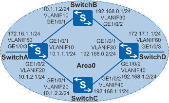
As shown in Figure 1, four switches all belong to Area0 on the OSPF network. Load balancing needs to be configured so that the traffic from SwitchA is sent to SwitchD through SwitchB and SwitchC.

In this scenario, ensure that all connected interfaces have STP disabled. If STP is enabled and VLANIF interfaces of switches are used to construct a Layer 3 ring network, an interface on the network will be blocked. As a result, Layer 3 services on the network cannot run normally.
Configuration Roadmap
The configuration roadmap is as follows:
Configure basic OSPF functions on each switch to implement basic connections on the OSPF network.
- Configure load balancing on SwitchA.
Procedure
- Configure VLANs to which each interface belongs.
# Configure SwitchA. The configurations of SwitchB, SwitchC, and SwitchD are similar.
<HUAWEI> system-view
[HUAWEI] sysname SwitchA
[SwitchA] vlan batch 10 20 50
[SwitchA] interface gigabitethernet 1/0/1
[SwitchA-GigabitEthernet1/0/1] port link-type trunk
[SwitchA-GigabitEthernet1/0/1] port trunk allow-pass vlan 10
[SwitchA-GigabitEthernet1/0/1] quit
[SwitchA] interface gigabitethernet 1/0/2
[SwitchA-GigabitEthernet1/0/2] port link-type trunk
[SwitchA-GigabitEthernet1/0/2] port trunk allow-pass vlan 20
[SwitchA-GigabitEthernet1/0/2] quit
[SwitchA] interface gigabitethernet 1/0/3
[SwitchA-GigabitEthernet1/0/3] port link-type trunk
[SwitchA-GigabitEthernet1/0/3] port trunk allow-pass vlan 50
[SwitchA-GigabitEthernet1/0/3] quit
- Configure an IP address for each VLANIF interface.
# Configure SwitchA. The configurations of SwitchB, SwitchC, and SwitchD are similar.
[SwitchA] interface vlanif 10
[SwitchA-Vlanif10] ip address 10.1.1.1 24
[SwitchA-Vlanif10] quit
[SwitchA] interface vlanif 20
[SwitchA-Vlanif20] ip address 10.1.2.1 24
[SwitchA-Vlanif20] quit
[SwitchA] interface vlanif 50
[SwitchA-Vlanif50] ip address 172.16.1.1 24
[SwitchA-Vlanif50] quit
- Configure basic OSPF functions.
# Configure SwitchA.
[SwitchA] ospf 1 router-id 10.10.10.1
[SwitchA-ospf-1] area 0
[SwitchA-ospf-1-area-0.0.0.0] network 172.16.1.0 0.0.0.255
[SwitchA-ospf-1-area-0.0.0.0] network 10.1.1.0 0.0.0.255
[SwitchA-ospf-1-area-0.0.0.0] network 10.1.2.0 0.0.0.255
[SwitchA-ospf-1-area-0.0.0.0] quit
[SwitchA-ospf-1] quit
# Configure SwitchB.
[SwitchB] ospf 1 router-id 10.10.10.2
[SwitchB-ospf-1] area 0
[SwitchB-ospf-1-area-0.0.0.0] network 10.1.1.0 0.0.0.255
[SwitchB-ospf-1-area-0.0.0.0] network 192.168.0.0 0.0.0.255
[SwitchB-ospf-1-area-0.0.0.0] quit
[SwitchB-ospf-1] quit
# Configure SwitchC.
[SwitchC] ospf 1 router-id 10.10.10.3
[SwitchC-ospf-1] area 0
[SwitchC-ospf-1-area-0.0.0.0] network 10.1.2.0 0.0.0.255
[SwitchC-ospf-1-area-0.0.0.0] network 192.168.1.0 0.0.0.255
[SwitchC-ospf-1-area-0.0.0.0] quit
[SwitchC-ospf-1] quit
# Configure SwitchD.
[SwitchD] ospf 1 router-id 10.10.10.4
[SwitchD-ospf-1] area 0
[SwitchD-ospf-1-area-0.0.0.0] network 192.168.0.0 0.0.0.255
[SwitchD-ospf-1-area-0.0.0.0] network 192.168.1.0 0.0.0.255
[SwitchD-ospf-1-area-0.0.0.0] network 172.17.1.0 0.0.0.255
[SwitchD-ospf-1-area-0.0.0.0] quit
[SwitchD-ospf-1] quit
# Display the routing table of SwitchA.
[SwitchA] display ip routing-table
Route Flags: R - relay, D - download to fib, T - to vpn-instance
------------------------------------------------------------------------------
Routing Tables: Public
         Destinations : 11       Routes : 12

Destination/Mask    Proto   Pre  Cost      Flags NextHop         Interface

       10.1.1.0/24  Direct  0    0           D   10.1.1.1        Vlanif10
       10.1.1.1/32  Direct  0    0           D   127.0.0.1       Vlanif10
       10.1.2.0/24  Direct  0    0           D   10.1.2.1        Vlanif20
       10.1.2.1/32  Direct  0    0           D   127.0.0.1       Vlanif20
      127.0.0.0/8   Direct  0    0           D   127.0.0.1       InLoopBack0
      127.0.0.1/32  Direct  0    0           D   127.0.0.1       InLoopBack0
     172.16.1.0/24  Direct  0    0           D   172.16.1.1      Vlanif50
     172.16.1.1/32  Direct  0    0           D   127.0.0.1       Vlanif50
     172.17.1.0/24  OSPF    10   3           D   10.1.2.2        Vlanif20
                    OSPF    10   3           D   10.1.1.2        Vlanif10
    192.168.0.0/24  OSPF    10   2           D   10.1.1.2        Vlanif10
    192.168.1.0/24  OSPF    10   2           D   10.1.2.2        Vlanif20
As shown in the routing table, two next hops 10.1.1.2 (SwitchB) and 10.1.2.2 (SwitchC) of SwitchA both become valid routes.
- Configure the weight of equal-cost routes on SwitchA.
If you do not want to implement load balancing between SwitchB and SwitchC, set the weight of equal-cost routes to specify the next hop.
[SwitchA] ospf 1
[SwitchA-ospf-1] nexthop 10.1.2.2 weight 1   //Specify the weight parameter to set the priority of equal-cost routes. The default weight value is 255. A larger priority value indicates a lower priority.
[SwitchA-ospf-1] quit
# Check the routing table on SwitchA.
[SwitchA] display ip routing-table
Route Flags: R - relay, D - download to fib, T - to vpn-instance
------------------------------------------------------------------------------
Routing Tables: Public
         Destinations : 11       Routes : 11

Destination/Mask    Proto   Pre  Cost      Flags NextHop         Interface

       10.1.1.0/24  Direct  0    0           D   10.1.1.1        Vlanif10
       10.1.1.1/32  Direct  0    0           D   127.0.0.1       Vlanif10
       10.1.2.0/24  Direct  0    0           D   10.1.2.1        Vlanif20
       10.1.2.1/32  Direct  0    0           D   127.0.0.1       Vlanif20
      127.0.0.0/8   Direct  0    0           D   127.0.0.1       InLoopBack0
      127.0.0.1/32  Direct  0    0           D   127.0.0.1       InLoopBack0
     172.16.1.0/24  Direct  0    0           D   172.16.1.1      Vlanif50
     172.16.1.1/32  Direct  0    0           D   127.0.0.1       Vlanif50
     172.17.1.0/24  OSPF    10   3           D   10.1.2.2        Vlanif20
    192.168.0.0/24  OSPF    10   2           D   10.1.1.2        Vlanif10
    192.168.1.0/24  OSPF    10   2           D   10.1.2.2        Vlanif20
As shown in the routing table, the priority of the next hop 10.1.2.2 (SwitchC) with the weight 1 is higher than that of 10.1.1.2 (SwitchB), after the weight is set for equal-cost routes. OSPF selects the route with the next hop 10.1.2.2 as the optimal route.
Configuration Files
SwitchA configuration file
#
sysname SwitchA
#
vlan batch 10 20 50
#
interface Vlanif10
 ip address 10.1.1.1 255.255.255.0
#
interface Vlanif20
 ip address 10.1.2.1 255.255.255.0
#
interface Vlanif50
 ip address 172.16.1.1 255.255.255.0
#
interface GigabitEthernet1/0/1
 port link-type trunk
 port trunk allow-pass vlan 10
#
interface GigabitEthernet1/0/2
 port link-type trunk
 port trunk allow-pass vlan 20
#
interface GigabitEthernet1/0/3
 port link-type trunk
 port trunk allow-pass vlan 50
#
ospf 1 router-id 10.10.10.1
 nexthop 10.1.2.2 weight 1
 area 0.0.0.0
  network 10.1.1.0 0.0.0.255
  network 10.1.2.0 0.0.0.255
  network 172.16.1.0 0.0.0.255
#
return
SwitchB configuration file
#
sysname SwitchB
#
vlan batch 10 30
#
interface Vlanif10
 ip address 10.1.1.2 255.255.255.0
#
interface Vlanif30
 ip address 192.168.0.1 255.255.255.0
#
interface GigabitEthernet1/0/1
 port link-type trunk
 port trunk allow-pass vlan 10
#
interface GigabitEthernet1/0/2
 port link-type trunk
 port trunk allow-pass vlan 30
#
ospf 1 router-id 10.10.10.2
 area 0.0.0.0
  network 10.1.1.0 0.0.0.255
  network 192.168.0.0 0.0.0.255
#
return
SwitchC configuration file
#
sysname SwitchC
#
vlan batch 20 40
#
interface Vlanif20
 ip address 10.1.2.2 255.255.255.0
#
interface Vlanif40
 ip address 192.168.1.1 255.255.255.0
#
interface GigabitEthernet1/0/1
 port link-type trunk
 port trunk allow-pass vlan 20
#
interface GigabitEthernet1/0/2
 port link-type trunk
 port trunk allow-pass vlan 40
#
ospf 1 router-id 10.10.10.3
 area 0.0.0.0
  network 10.1.2.0 0.0.0.255
  network 192.168.1.0 0.0.0.255
#
return
SwitchD configuration file
#
sysname SwitchD
#
vlan batch 30 40 60
#
interface Vlanif30
 ip address 192.168.0.2 255.255.255.0
#
interface Vlanif40
 ip address 192.168.1.2 255.255.255.0
#
interface Vlanif60
 ip address 172.17.1.1 255.255.255.0
#
interface GigabitEthernet1/0/1
 port link-type trunk
 port trunk allow-pass vlan 30
#
interface GigabitEthernet1/0/2
 port link-type trunk
 port trunk allow-pass vlan 40
#
interface GigabitEthernet1/0/3
 port link-type trunk
 port trunk allow-pass vlan 60
#
ospf 1 router-id 10.10.10.4
 area 0.0.0.0
  network 172.17.1.0 0.0.0.255
  network 192.168.0.0 0.0.0.255
  network 192.168.1.0 0.0.0.255
#
return
Applicable Products and Versions
Product |
Product Model |
Software Version |
|---|---|---|
S3700 |
S3700-EI |
V100R006C05 |
S3700-HI |
V200R001C00 |
|
S5700 |
S5700-EI |
V200R001(C00&C01), V200R002C00, V200R003C00, V200R005(C00&C01&C02&C03) |
S5710-EI |
V200R001C00, V200R002C00, V200R003C00, V200R005(C00&C02) |
|
S5720-EI |
V200R007C00, V200R008C00, V200R009C00, V200R010C00, V200R011C00, V200R011C10, V200R012C00, V200R013C00, V200R019C00, V200R019C10 |
|
S5720-SI, S5720S-SI |
V200R008C00, V200R009C00, V200R010C00, V200R011C00, V200R011C10, V200R012C00, V200R013C00, V200R019C00, V200R019C10 |
|
S5720I-SI |
V200R012C00, V200R013C00, V200R019C00, V200R019C10 |
|
S5730-SI |
V200R011C10, V200R012C00, V200R013C00, V200R019C00, V200R019C10 |
|
S5730S-EI |
V200R011C10, V200R012C00, V200R013C00, V200R019C00, V200R019C10 |
|
S5700-HI |
V200R001(C00&C01), V200R002C00, V200R003C00, V200R005(C00SPC500&C01&C02) |
|
S5710-HI |
V200R003C00, V200R005(C00&C02&C03) |
|
S5720-HI |
V200R006C00, V200R007(C00&C10), V200R008C00, V200R009C00, V200R010C00, V200R011C00, V200R011C10, V200R012C00, V200R013C00, V200R019C00, V200R019C10 |
|
S5730-HI |
V200R012C00, V200R013C00, V200R019C00, V200R019C10 |
|
S5731-H |
V200R013C02, V200R019C00, V200R019C10 |
|
S5731-S, S5731S-S |
V200R019C00, V200R019C10 |
|
S5731S-H |
V200R019C00, V200R019C10 |
|
S5732-H |
V200R019C00, V200R019C10 |
|
S5735-S, S5735S-S |
V200R019C00, V200R019C10 |
|
S5700 |
S5735-S-I |
V200R019C10 |
S6700 |
S6700-EI |
V200R001(C00&C01), V200R002C00, V200R003C00, V200R005(C00&C01&C02) |
S6720-EI |
V200R008C00, V200R009C00, V200R010C00, V200R011C00, V200R011C10, V200R012C00, V200R013C00, V200R019C00, V200R019C10 |
|
S6720S-EI |
V200R009C00, V200R010C00, V200R011C00, V200R011C10, V200R012C00, V200R013C00, V200R019C00, V200R019C10 |
|
S6720-SI, S6720S-SI |
V200R011C00, V200R011C10, V200R012C00, V200R013C00, V200R019C00, V200R019C10 |
|
S6720-HI |
V200R012C00, V200R013C00, V200R019C00, V200R019C10 |
|
S6730-H |
V200R013C02, V200R019C00, V200R019C10 |
|
S6730S-H |
V200R019C10 |
|
S6730-S, S6730S-S |
V200R019C00, V200R019C10 |
|
S7700 |
S7703, S7706, S7712 |
V200R001(C00&C01), V200R002C00, V200R003C00, V200R005C00, V200R006C00, V200R007C00, V200R008C00, V200R009C00, V200R010C00, V200R011C10, V200R012C00, V200R013C00, V200R013C02, V200R019C00, V200R019C10 |
S7703 PoE |
V200R013C00, V200R019C00, V200R019C10 |
|
S7706 PoE |
V200R013C00, V200R019C00, V200R019C10 |
|
S9700 |
S9703, S9706, S9712 |
V200R001(C00&C01), V200R002C00, V200R003C00, V200R005C00, V200R006C00, V200R007(C00&C10), V200R008C00, V200R009C00, V200R010C00, V200R011C10, V200R012C00, V200R013C00 |
For details about software mappings, visit Hardware Query Tool and search for the desired product model.