Example for Configuring BFD for OSPF
BFD for OSPF Overview
Bidirectional forwarding detection (BFD) is a mechanism used to detect communication faults between forwarding engines. BFD detects connectivity of a data protocol on a path between two systems. The path can be a physical or logical link. In BFD for OSPF, a BFD session is associated with OSPF. The BFD session quickly detects a link fault and then notifies OSPF of the fault. This speeds up OSPF's response to the change of the network topology.
Any link fault or topology change on the network will cause the device to recalculate routes. If the OSPF detection mechanism is used, the route recalculation time is the OSPF protocol convergence time. In this case, OSPF detects faults in seconds. In high-speed data transmission, for example, at gigabit rates, a detection time longer than one second results in the loss of a large amount of data. In delay-sensitive services such as voice, a delay longer than one second is unacceptable. When an OSPF network requires high reliability or the services running on the network are delay-sensitive, BFD for OSPF can be configured. BFD speeds up OSPF network convergence and then OSPF can detect the fault in milliseconds if a fault occurs in the link between neighbors.
Configuration Notes
- BFD needs to be configured on the two ends between which the OSPF neighbor relationship is established.
- The two ends that establish BFD sessions must be located in the same network segment on an OSPF area.
- The ospf bfd enable and ospf bfd block commands are mutually exclusive and cannot be enabled at the same time.
- For the fixed switch models and versions that support this example, see Applicable Products and Versions.
Networking Requirements
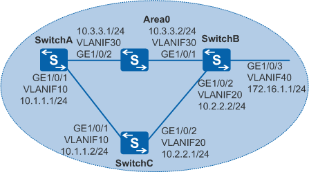
As shown in Figure 1, OSPF runs among SwitchA, SwitchB, and SwitchC, and the switch between SwitchA and SwitchB only provides the transparent transmission function. SwitchA and SwitchB need to quickly detect the status of the link between them. When the link SwitchA->SwitchB is faulty, services can be quickly switched to the backup link SwitchA->SwitchC->SwitchB.

In this scenario, ensure that all connected interfaces have STP disabled. If STP is enabled and VLANIF interfaces of switches are used to construct a Layer 3 ring network, an interface on the network will be blocked. As a result, Layer 3 services on the network cannot run normally.
Configuration Roadmap
The configuration roadmap is as follows:
Configure basic OSPF functions on SwitchA, SwitchB, and SwitchC to implement basic connections on the OSPF network.
Configure BFD for OSPF on SwitchA, SwitchB, and SwitchC so that services can be quickly switched to the backup link when the link between SwitchA and SwitchB is faulty.
Procedure
- Configure VLANs to which each interface belongs.
# Configure SwitchA. The configurations of SwitchB and SwitchC are the same as the configuration of SwitchA.
<HUAWEI> system-view
[HUAWEI] sysname SwitchA
[SwitchA] vlan batch 10 30
[SwitchA] interface gigabitethernet 1/0/1
[SwitchA-GigabitEthernet1/0/1] port link-type trunk
[SwitchA-GigabitEthernet1/0/1] port trunk allow-pass vlan 10
[SwitchA-GigabitEthernet1/0/1] quit
[SwitchA] interface gigabitethernet 1/0/2
[SwitchA-GigabitEthernet1/0/2] port link-type trunk
[SwitchA-GigabitEthernet1/0/2] port trunk allow-pass vlan 30
[SwitchA-GigabitEthernet1/0/2] quit
- Configure an IP address for each VLANIF interface.
# Configure SwitchA. The configurations of SwitchB and SwitchC are similar.
[SwitchA] interface vlanif 10
[SwitchA-Vlanif10] ip address 10.1.1.1 24
[SwitchA-Vlanif10] quit
[SwitchA] interface vlanif 30
[SwitchA-Vlanif30] ip address 10.3.3.1 24
[SwitchA-Vlanif30] quit
- Configure basic OSPF functions.
# Configure SwitchA.
[SwitchA] ospf 1 router-id 10.10.10.1
[SwitchA-ospf-1] area 0
[SwitchA-ospf-1-area-0.0.0.0] network 10.1.1.0 0.0.0.255
[SwitchA-ospf-1-area-0.0.0.0] network 10.3.3.0 0.0.0.255
[SwitchA-ospf-1-area-0.0.0.0] quit
[SwitchA-ospf-1] quit
# Configure SwitchB.
[SwitchB] ospf 1 router-id 10.10.10.2
[SwitchB-ospf-1] area 0
[SwitchB-ospf-1-area-0.0.0.0] network 10.2.2.0 0.0.0.255
[SwitchB-ospf-1-area-0.0.0.0] network 10.3.3.0 0.0.0.255
[SwitchB-ospf-1-area-0.0.0.0] network 172.16.1.0 0.0.0.255
[SwitchB-ospf-1-area-0.0.0.0] quit
[SwitchB-ospf-1] quit
# Configure SwitchC.
[SwitchC] ospf 1 router-id 10.10.10.3
[SwitchC-ospf-1] area 0
[SwitchC-ospf-1-area-0.0.0.0] network 10.1.1.0 0.0.0.255
[SwitchC-ospf-1-area-0.0.0.0] network 10.2.2.0 0.0.0.255
[SwitchC-ospf-1-area-0.0.0.0] quit
[SwitchC-ospf-1] quit
# After the preceding configurations, run the display ospf peer command. The neighbor relationships are set up among SwitchA, SwitchB, and SwitchC. The command output of SwitchA is used as an example.
[SwitchA] display ospf peer

          OSPF Process 1 with Router ID 10.10.10.1
                  Neighbors

 Area 0.0.0.0 interface 10.1.1.1(Vlanif10)'s neighbors
 Router ID: 10.10.10.3       Address: 10.1.1.2
   State: Full  Mode:Nbr is  Master  Priority: 1
   DR: 10.1.1.2  BDR: 10.1.1.1  MTU: 0
   Dead timer due in 38  sec
   Retrans timer interval: 5
   Neighbor is up for 00:00:15
   Authentication Sequence: [ 0 ]

                  Neighbors

 Area 0.0.0.0 interface 10.3.3.1(Vlanif30)'s neighbors
 Router ID: 10.10.10.2       Address: 10.3.3.2
   State: Full  Mode:Nbr is   Master  Priority: 1
   DR: 10.3.3.2  BDR: 10.3.3.1  MTU: 0
   Dead timer due in 25  sec
   Retrans timer interval: 5
   Neighbor is up for 00:00:59
   Authentication Sequence: [ 0 ]
# Check the OSPF routing table on SwitchA. You can see the routing entries to SwitchB and SwitchC. However, the next-hop address of the route to the destination network segment 172.16.1.0/24 is 10.3.3.2, which indicates that the traffic is transmitted on the link SwitchA→SwitchB.
[SwitchA] display ospf routing

          OSPF Process 1 with Router ID 10.10.10.1
                   Routing Tables

 Routing for Network
 Destination        Cost  Type       NextHop         AdvRouter       Area
 10.1.1.0/24        1     Transit    10.1.1.1        10.10.10.1      0.0.0.0
 10.3.3.0/24        1     Transit    10.3.3.1        10.10.10.1      0.0.0.0
 10.2.2.0/24        2     Transit    10.1.1.2        10.10.10.3      0.0.0.0
 10.2.2.0/24        2     Transit    10.3.3.2        10.10.10.3      0.0.0.0
 172.16.1.0/24      2     Stub       10.3.3.2        10.10.10.2      0.0.0.0

 Total Nets: 5
 Intra Area: 5  Inter Area: 0  ASE: 0  NSSA: 0
- Configure BFD for OSPF.
# Configure BFD for OSPF on SwitchA.
[SwitchA] bfd   //Enable BFD globally.
[SwitchA-bfd] quit
[SwitchA] ospf 1
[SwitchA-ospf-1] bfd all-interfaces enable   //Enable BFD in OSPF process 1.
[SwitchA-ospf-1] quit
# Configure BFD for OSPF on SwitchB.
[SwitchB] bfd   //Enable BFD globally.
[SwitchB-bfd] quit
[SwitchB] ospf 1
[SwitchB-ospf-1] bfd all-interfaces enable   //Enable BFD in OSPF process 1.
[SwitchB-ospf-1] quit
# Configure BFD for OSPF on SwitchC.
[SwitchC] bfd   //Enable BFD globally.
[SwitchC-bfd] quit
[SwitchC] ospf 1
[SwitchC-ospf-1] bfd all-interfaces enable   //Enable BFD in OSPF process 1.
[SwitchC-ospf-1] quit
# After the preceding configurations, run the display ospf bfd session all command on SwitchA, SwitchB, or SwitchC. The peer BFD session is Up. The command output of SwitchA is used as an example.
[SwitchA] display ospf bfd session all

          OSPF Process 1 with Router ID 10.10.10.1
  Area 0.0.0.0 interface 10.1.1.1(Vlanif10)'s BFD Sessions

 NeighborId:10.10.10.3       AreaId:0.0.0.0          Interface:Vlanif10
 BFDState:up                 rx    :1000             tx       :1000
 Multiplier:3                BFD Local Dis:8195      LocalIpAdd:10.1.1.1
 RemoteIpAdd:10.1.1.2        Diagnostic Info:No diagnostic information

  Area 0.0.0.0 interface 10.3.3.1(Vlanif30)'s BFD Sessions

 NeighborId:10.10.10.2       AreaId:0.0.0.0          Interface:Vlanif30
 BFDState:up                 rx    :1000             tx       :1000
 Multiplier:3                BFD Local Dis:8194      LocalIpAdd:10.3.3.1
 RemoteIpAdd:10.3.3.2         Diagnostic Info:No diagnostic information
- Verify the configuration.
# Run the shutdown command on GE1/0/1 of SwitchB to simulate the link fault.
[SwitchB] interface gigabitethernet 1/0/1
[SwitchB-GigabitEthernet1/0/1] shutdown
# Check the OSPF routing table on SwitchA.
[SwitchA] display ospf routing

          OSPF Process 1 with Router ID 10.10.10.1
                   Routing Tables

 Routing for Network
 Destination        Cost  Type       NextHop         AdvRouter       Area
 10.1.1.0/24        1     Transit    10.1.1.1        10.10.10.1      0.0.0.0
 10.2.2.0/24        2     Transit    10.1.1.2        10.10.10.3      0.0.0.0
 172.16.1.0/24      3     Stub       10.1.1.2        10.10.10.2      0.0.0.0

 Total Nets: 3
 Intra Area: 3  Inter Area: 0  ASE: 0  NSSA: 0
When the link SwitchA->SwitchB is faulty, the backup link SwitchA->SwitchC->SwitchB takes effect and the next-hop address of the route to the destination network segment 172.16.1.0/24 changes to 10.1.1.2.
Configuration Files
SwitchA configuration file
#
sysname SwitchA
#
vlan batch 10 30
#
bfd
#
interface Vlanif10
 ip address 10.1.1.1 255.255.255.0
#
interface Vlanif30
 ip address 10.3.3.1 255.255.255.0
#
interface GigabitEthernet1/0/1
 port link-type trunk
 port trunk allow-pass vlan 10
#
interface GigabitEthernet1/0/2
 port link-type trunk
 port trunk allow-pass vlan 30
#
ospf 1 router-id 10.10.10.1
 bfd all-interfaces enable
 area 0.0.0.0
  network 10.1.1.0 0.0.0.255
  network 10.3.3.0 0.0.0.255
#
return
SwitchB configuration file
#
sysname SwitchB
#
vlan batch 20 30 40
#
bfd
#
interface Vlanif20
 ip address 10.2.2.2 255.255.255.0
#
interface Vlanif30
 ip address 10.3.3.2 255.255.255.0
#
interface Vlanif40
 ip address 172.16.1.1 255.255.255.0
#
interface GigabitEthernet1/0/1
 port link-type trunk
 port trunk allow-pass vlan 30
#
interface GigabitEthernet1/0/2
 port link-type trunk
 port trunk allow-pass vlan 20
#
interface GigabitEthernet1/0/3
 port link-type trunk
 port trunk allow-pass vlan 40
#
ospf 1 router-id 10.10.10.2
 bfd all-interfaces enable
 area 0.0.0.0
  network 10.2.2.0 0.0.0.255
  network 10.3.3.0 0.0.0.255
  network 172.16.1.0 0.0.0.255
#
return
SwitchC configuration file
#
sysname SwitchC
#
vlan batch 10 20
#
bfd
#
interface Vlanif10
 ip address 10.1.1.2 255.255.255.0
#
interface Vlanif20
 ip address 10.2.2.1 255.255.255.0
#
interface GigabitEthernet1/0/1
 port link-type trunk
 port trunk allow-pass vlan 10
#
interface GigabitEthernet1/0/2
 port link-type trunk
 port trunk allow-pass vlan 20
#
ospf 1 router-id 10.10.10.3
 bfd all-interfaces enable
 area 0.0.0.0
  network 10.1.1.0 0.0.0.255
  network 10.2.2.0 0.0.0.255
#
return
Applicable Products and Versions
Product |
Product Model |
Software Version |
|---|---|---|
S3700 |
S3700-EI |
V100R006C05 |
S3700-HI |
V200R001C00 |
|
S5700 |
S5700-EI |
V200R001(C00&C01), V200R002C00, V200R003C00, V200R005(C00&C01&C02&C03) |
S5710-EI |
V200R001C00, V200R002C00, V200R003C00, V200R005(C00&C02) |
|
S5720-EI |
V200R007C00, V200R008C00, V200R009C00, V200R010C00, V200R011C00, V200R011C10, V200R012C00, V200R013C00, V200R019C00, V200R019C10 |
|
S5720-SI, S5720S-SI |
V200R008C00, V200R009C00, V200R010C00, V200R011C00, V200R011C10, V200R012C00, V200R013C00, V200R019C00, V200R019C10 |
|
S5720I-SI |
V200R012C00, V200R013C00, V200R019C00, V200R019C10 |
|
S5730-SI |
V200R011C10, V200R012C00, V200R013C00, V200R019C00, V200R019C10 |
|
S5730S-EI |
V200R011C10, V200R012C00, V200R013C00, V200R019C00, V200R019C10 |
|
S5700-HI |
V200R001(C00&C01), V200R002C00, V200R003C00, V200R005(C00SPC500&C01&C02) |
|
S5710-HI |
V200R003C00, V200R005(C00&C02&C03) |
|
S5720-HI |
V200R006C00, V200R007(C00&C10), V200R008C00, V200R009C00, V200R010C00, V200R011C00, V200R011C10, V200R012C00, V200R013C00, V200R019C00, V200R019C10 |
|
S5730-HI |
V200R012C00, V200R013C00, V200R019C00, V200R019C10 |
|
S5731-H |
V200R013C02, V200R019C00, V200R019C10 |
|
S5731-S, S5731S-S |
V200R019C00, V200R019C10 |
|
S5731S-H |
V200R019C00, V200R019C10 |
|
S5732-H |
V200R019C00, V200R019C10 |
|
S5735-S, S5735S-S |
V200R019C00, V200R019C10 |
|
S5700 |
S5735-S-I |
V200R019C10 |
S6700 |
S6700-EI |
V200R001(C00&C01), V200R002C00, V200R003C00, V200R005(C00&C01&C02) |
S6720-EI |
V200R008C00, V200R009C00, V200R010C00, V200R011C00, V200R011C10, V200R012C00, V200R013C00, V200R019C00, V200R019C10 |
|
S6720S-EI |
V200R009C00, V200R010C00, V200R011C00, V200R011C10, V200R012C00, V200R013C00, V200R019C00, V200R019C10 |
|
S6720-SI, S6720S-SI |
V200R011C00, V200R011C10, V200R012C00, V200R013C00, V200R019C00, V200R019C10 |
|
S6720-HI |
V200R012C00, V200R013C00, V200R019C00, V200R019C10 |
|
S6730-H |
V200R013C02, V200R019C00, V200R019C10 |
|
S6730S-H |
V200R019C10 |
|
S6730-S, S6730S-S |
V200R019C00, V200R019C10 |
|
S7700 |
S7703, S7706, S7712 |
V200R001(C00&C01), V200R002C00, V200R003C00, V200R005C00, V200R006C00, V200R007C00, V200R008C00, V200R009C00, V200R010C00, V200R011C10, V200R012C00, V200R013C00, V200R013C02, V200R019C00, V200R019C10 |
S7703 PoE |
V200R013C00, V200R019C00, V200R019C10 |
|
S7706 PoE |
V200R013C00, V200R019C00, V200R019C10 |
|
S9700 |
S9703, S9706, S9712 |
V200R001(C00&C01), V200R002C00, V200R003C00, V200R005C00, V200R006C00, V200R007(C00&C10), V200R008C00, V200R009C00, V200R010C00, V200R011C10, V200R012C00, V200R013C00 |
For details about software mappings, visit Hardware Query Tool and search for the desired product model.