Example for Configuring RRPP Snooping on a VPLS Network
Overview
RRPP snooping notifies a VPLS network of changes in an RRPP ring. After RRPP snooping is enabled on sub-interfaces or VLANIF interfaces, the VPLS network can transparently transmit RRPP packets, detect changes in the RRPP ring, and update forwarding entries. This ensures that traffic can be rapidly switched to a non-blocking path.
In Figure 1, UPEs constitute an RRPP ring and connect to the VPLS network where NPEs are located. NPEs are connected through a PW, so they cannot serve as RRPP nodes to respond to RRPP packets. As a result, the VPLS network cannot detect changes to the RRPP ring status. When the RRPP ring topology changes, each node on the VPLS network forwards downstream data according to the MAC address table generated before the RRPP ring topology changes. Consequently, the downstream traffic cannot be forwarded
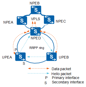
You can enable RRPP snooping on the sub-interface or VLANIF interface of NPED and associate the interface with VSIs on the local device. When the RRPP ring is faulty, NPED on the VPLS network deletes forwarding entries of VSIs (including the associated VSIs) on the local node and forwarding entries of NPEB to re-learn forwarding entries. This ensures that traffic can be switched to a normal path and downstream traffic can be properly forwarded.
Configuration Notes
- RRPP and RRPP snooping cannot be configured on the same interface.
- SA series cards and XGE interfaces connected to ET1D2IPS0S00, ET1D2FW00S00, ET1D2FW00S01, ET1D2FW00S02, and ACU2 cards do not support RRPP snooping. In earlier versions of V200R007C00, X1E series cards do not support RRPP snooping.
For applicable product models and versions, see Applicable Product Models and Versions.

For details about software mappings, visit Hardware Query Tool and search for the desired product model.
Networking Requirements
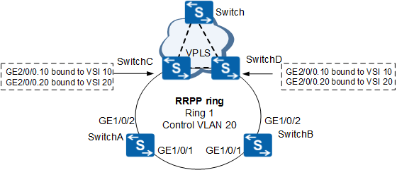
In Figure 2, SwitchA, SwitchB, SwitchC, and SwitchD constitute an RRPP ring. The network is required to prevent loops when the ring is complete and to implement fast convergence to rapidly restore communication between nodes in the ring when the ring fails. The VPLS network can transparently transmit RRPP packets, detect RRPP ring status changes, and update forwarding entries so that traffic can be rapidly switched to a normal path according to the ring status.
Configuration Roadmap
The configuration roadmap is as follows:
Configure a VPLS network.
Configure an RRPP ring to prevent loops and implement fast convergence when a device fails.
Enable RRPP snooping so that the VPLS network can transparently transmit RRPP packets and detect RRPP ring status change.
Associate interfaces with VSIs so that SwitchC and SwitchD on the VPLS network can delete the MAC address tables of their VSIs when a fault occurs on the RRPP ring network.
VLAN termination sub-interfaces can be created on a non-VCMP client.
Procedure
- Configure VPLS. SwitchC is used as an example. The configuration of SwitchD is similar to the configuration of SwitchC, and is not mentioned here. For details, see the configuration files.
This example provides only configurations of sub-interfaces on SwitchC and SwitchD connected to the RRPP ring. The configurations of devices on the VPLS network are not mentioned.
# Configure GE2/0/0.10 on SwitchC to allow the packets of VLAN 10 to pass through and bind GE2/0/0.10 to VSI 10.
<HUAWEI> system-view
[HUAWEI] sysname SwitchC
[SwitchC] interface gigabitethernet 2/0/0
[SwitchC-GigabitEthernet2/0/0] undo portswitch
[SwitchC-GigabitEthernet2/0/0] quit
[SwitchC] interface gigabitethernet 2/0/0.10
[SwitchC-GigabitEthernet2/0/0.10] dot1q termination vid 10
[SwitchC-GigabitEthernet2/0/0.10] l2 binding vsi VSI10  //Bind a VSI to the sub-interface.
[SwitchC-GigabitEthernet2/0/0.10] quit
# Configure GE2/0/0.20 on SwitchC to allow packets of VLAN 20 (control VLAN of RRPP) to pass through and bind GE2/0/0.20 to VSI 20.
[SwitchC] interface gigabitethernet 2/0/0.20
[SwitchC-GigabitEthernet2/0/0.20] dot1q termination vid 20
[SwitchC-GigabitEthernet2/0/0.20] l2 binding vsi VSI20
[SwitchC-GigabitEthernet2/0/0.20] quit
- Create an RRPP domain and its control VLAN.
# Create VLAN 10 on SwitchA.
<HUAWEI> system-view
[HUAWEI] sysname SwitchA
[SwitchA] vlan batch 10
[SwitchA] stp region-configuration
[SwitchA-mst-region] instance 1 vlan 10 20 21  //Add the major control VLAN, sub-control VLAN, and data VLAN to instance 1.
[SwitchA-mst-region] active region-configuration
[SwitchA-mst-region] quit
# Configure SwitchA (master node in ring 1) in RRPP domain 1 and VLAN 20 as the control VLAN.
[SwitchA] rrpp domain 1
[SwitchA-rrpp-domain-region1] protected-vlan reference-instance 1  //Configure instance 1 as the protected instance of the RRPP domain.
[SwitchA-rrpp-domain-region1] control-vlan 20                      //Each RRPP domain has a major control VLAN and a sub-control VLAN. You only need to specify the major control VLAN. The system uses the VLAN whose ID is one greater than the ID of the major control VLAN as the sub-control VLAN.
[SwitchA-rrpp-domain-region1] quit
# Create VLAN 10 on SwitchB.
<HUAWEI> system-view
[HUAWEI] sysname SwitchB
[SwitchB] vlan batch 10
[SwitchB] stp region-configuration
[SwitchB-mst-region] instance 1 vlan 10 20 21
[SwitchB-mst-region] active region-configuration
[SwitchB-mst-region] quit
# Configure SwitchB (transit node in ring 1) in RRPP domain 1 and VLAN 20 as the control VLAN.
[SwitchB] rrpp domain 1
[SwitchB-rrpp-domain-region1] protected-vlan reference-instance 1
[SwitchB-rrpp-domain-region1] control-vlan 20
[SwitchB-rrpp-domain-region1] quit
- Disable STP on the interfaces to be added to the RRPP ring.
# Disable STP on the interfaces to be added to the RRPP ring on SwitchA.
[SwitchA] interface gigabitethernet 1/0/1
[SwitchA-GigabitEthernet1/0/1] port link-type trunk
[SwitchA-GigabitEthernet1/0/1] port trunk allow-pass vlan 10
[SwitchA-GigabitEthernet1/0/1] stp disable
[SwitchA-GigabitEthernet1/0/1] quit
[SwitchA] interface gigabitethernet 1/0/2
[SwitchA-GigabitEthernet1/0/2] port link-type trunk
[SwitchA-GigabitEthernet1/0/2] port trunk allow-pass vlan 10
[SwitchA-GigabitEthernet1/0/2] stp disable
[SwitchA-GigabitEthernet1/0/2] quit
# Disable STP on the interfaces to be added to the RRPP ring on SwitchB.
[SwitchB] interface gigabitethernet 1/0/1
[SwitchB-GigabitEthernet1/0/1] port link-type trunk
[SwitchB-GigabitEthernet1/0/1] port trunk allow-pass vlan 10
[SwitchB-GigabitEthernet1/0/1] stp disable
[SwitchB-GigabitEthernet1/0/1] quit
[SwitchB] interface gigabitethernet 1/0/2
[SwitchB-GigabitEthernet1/0/2] port link-type trunk
[SwitchB-GigabitEthernet1/0/2] port trunk allow-pass vlan 10
[SwitchB-GigabitEthernet1/0/2] stp disable
[SwitchB-GigabitEthernet1/0/2] quit
- Create an RRPP ring.
# Configure SwitchA as the master node in ring 1 and specify the primary and secondary interfaces.
[SwitchA] rrpp domain 1
[SwitchA-rrpp-domain-region1] ring 1 node-mode master primary-port gigabitethernet 1/0/1 secondary-port gigabitethernet 1/0/2 level 0
[SwitchA-rrpp-domain-region1] ring 1 enable
[SwitchA-rrpp-domain-region1] quit
# Configure SwitchB as a transit node in ring 1 (major ring) and specify the primary and secondary interfaces.
[SwitchB] rrpp domain 1
[SwitchB-rrpp-domain-region1] ring 1 node-mode transit primary-port gigabitethernet 1/0/1 secondary-port gigabitethernet 1/0/2 level 0
[SwitchB-rrpp-domain-region1] ring 1 enable
[SwitchB-rrpp-domain-region1] quit
- Enable RRPP.
# Enable RRPP on SwitchA.
[SwitchA] rrpp enable
# Enable RRPP on SwitchB.
[SwitchB] rrpp enable
- Configure RRPP snooping.
# Enable RRPP snooping on GE2/0/0.20 of SwitchC.
[SwitchC] interface gigabitethernet 2/0/0.20
[SwitchC-GigabitEthernet2/0/0.20] rrpp snooping enable
# Enable RRPP snooping on GE2/0/0.20 of SwitchD.
[SwitchD] interface gigabitethernet 2/0/0.20
[SwitchD-GigabitEthernet2/0/0.20] rrpp snooping enable
- Configure association between interfaces and VSIs.
# Associate VSI 10 with GE2/0/0.20 on SwitchC.
[SwitchC-GigabitEthernet2/0/0.20] rrpp snooping vsi VSI10
[SwitchC-GigabitEthernet2/0/0.20] quit
# Associate VSI 10 with GE2/0/0.20 on SwitchD.
[SwitchD-GigabitEthernet2/0/0.20] rrpp snooping vsi VSI10
[SwitchD-GigabitEthernet2/0/0.20] quit
- Verify the configuration.
After the configuration is complete and the network topology becomes stable, perform the following operations to verify the configuration. SwitchA is used as an example.
Run the display rrpp brief command on SwitchA. The following information is displayed:
[SwitchA] display rrpp brief
Abbreviations for Switch Node Mode :
M - Master , T - Transit , E - Edge , A - Assistant-Edge

RRPP Protocol Status: Enable
RRPP Working Mode: HW
RRPP Linkup Delay Timer: 0 sec (0 sec default)
Number of RRPP Domains: 1

Domain Index   : 1
Control VLAN   : major 20    sub 21
Protected VLAN : Reference Instance 1
Hello Timer    : 1 sec(default is 1 sec)  Fail Timer : 6 sec(default is 6 sec)

 Ring   Ring    Node     Primary/Common        Secondary/Edge        Is
 ID     Level   Mode     Port                  Port                  Enabled
 ----------------------------------------------------------------------------
 1      0       M        GigabitEthernet1/0/1  GigabitEthernet1/0/2  Yes
According to the preceding information, RRPP is enabled on SwitchA. The major control VLAN of RRPP domain 1 is VLAN 20 and the sub-control VLAN is VLAN 21. SwitchA is the master node in ring 1. The primary interface is GE1/0/1 and the secondary interface is GE1/0/2.
Run the display rrpp verbose domain command on SwitchA. The following information is displayed.
# Check detailed information about RRPP domain 1 on SwitchA.
[SwitchA] display rrpp verbose domain 1
Domain Index   : 1
Control VLAN   : major 20    sub 21
Protected VLAN : Reference Instance 1
Hello Timer    : 1 sec(default is 1 sec)  Fail Timer : 6 sec(default is 6 sec)

RRPP Ring      : 1
Ring Level     : 0
Node Mode      : Master
Ring State     : Complete
Is Enabled     : Enable                       Is Active : Yes
Primary port   : GigabitEthernet1/0/1         Port status: UP
Secondary port : GigabitEthernet1/0/2         Port status: BLOCKED
# Check the RRPP snooping configuration on GE2/0/0.20 of SwitchC.
[SwitchC] display rrpp snooping enable interface gigabitethernet 2/0/0.20
  Port                            VsiName           Vlan
---------------------------------------------------------------------------
  GigabitEthernet2/0/0.20         VSI20             20
The preceding information shows that VSI 20 and VLAN 20 are associated with GE2/0/0.20.
# Check information about other VSIs associated with GE2/0/0.20 on SwitchC.
[SwitchC] display rrpp snooping vsi interface gigabitethernet 2/0/0.20
  Port                               VsiName
---------------------------------------------------------------------
  GigabitEthernet2/0/0.20            VSI10
  GigabitEthernet2/0/0.20            VSI20
The preceding information shows that GE2/0/0.20 is associated with VSI 10 and VSI 20.
Configuration Files
SwitchA configuration file
#
sysname SwitchA
#
vlan batch 10 20 to 21
#
rrpp enable
#
stp region-configuration
 instance 1 vlan 10 20 to 21
 active region-configuration
#
rrpp domain 1
 control-vlan 20
 protected-vlan reference-instance 1
 ring 1 node-mode master primary-port GigabitEthernet1/0/1 secondary-port GigabitEthernet1/0/2 level 0
 ring 1 enable
#
interface GigabitEthernet1/0/1
 port link-type trunk
 port trunk allow-pass vlan 10 20 to 21
 stp disable
#
interface GigabitEthernet1/0/2
 port link-type trunk
 port trunk allow-pass vlan 10 20 to 21
 stp disable
#
return
SwitchB configuration file
#
sysname SwitchB
#
vlan batch 10 20 to 21
#
rrpp enable
#
stp region-configuration
 instance 1 vlan 10 20 to 21
 active region-configuration
#
rrpp domain 1
 control-vlan 20
 protected-vlan reference-instance 1
 ring 1 node-mode transit primary-port GigabitEthernet1/0/1 secondary-port GigabitEthernet1/0/2 level 0
 ring 1 enable
#
interface GigabitEthernet1/0/1
 port link-type trunk
 port trunk allow-pass vlan 10 20 to 21
 stp disable
#
interface GigabitEthernet1/0/2
 port link-type trunk
 port trunk allow-pass vlan 10 20 to 21
 stp disable
#
return
SwitchC configuration file
#
sysname SwitchC
#
interface GigabitEthernet2/0/0
 undo portswitch
#
interface GigabitEthernet2/0/0.10
 dot1q termination vid 10
 l2 binding vsi VSI10
#
interface GigabitEthernet2/0/0.20
 dot1q termination vid 20
 l2 binding vsi VSI20
 rrpp snooping enable
 rrpp snooping vsi VSI10
#
return
SwitchD configuration file
#
sysname SwitchD
#
interface GigabitEthernet2/0/0
 undo portswitch
#
interface GigabitEthernet2/0/0.10
 dot1q termination vid 10
 l2 binding vsi VSI10
#
interface GigabitEthernet2/0/0.20
 dot1q termination vid 20
 l2 binding vsi VSI20
 rrpp snooping enable
 rrpp snooping vsi VSI10
#
return
Applicable Product Models and Versions
Product |
Product Model |
Software Version |
|---|---|---|
S5700 |
S5700-HI |
V200R002C00, V200R003C00, V200R005(C00SPC500&C01&C02) |
S5710-EI |
V200R002C00, V200R003C00, V200R005(C00&C02) |
|
S5720-EI |
V200R009C00, V200R010C00, V200R011C00, V200R011C10, V200R012C00, V200R013C00, V200R019C00, V200R019C10 |
|
S5710-HI |
V200R003C00, V200R005(C00&C02&C03) |
|
S5720-HI |
V200R007C10, V200R009C00, V200R010C00, V200R011C00, V200R011C10, V200R012C00, V200R013C00, V200R019C00, V200R019C10 |
|
S5730-HI |
V200R012C00, V200R013C00, V200R019C00, V200R019C10 |
|
S5731-H |
V200R013C02, V200R019C00, V200R019C10 |
|
S5731S-H |
V200R019C00, V200R019C10 |
|
S5732-H |
V200R019C00, V200R019C10 |
|
S6700 |
S6700-EI |
V200R005(C00&C01) |
S6720-EI |
V200R008C00, V200R009C00, V200R010C00, V200R011C00, V200R011C10, V200R012C00, V200R013C00, V200R019C00, V200R019C10 |
|
S6720S-EI |
V200R009C00, V200R010C00, V200R011C00, V200R011C10, V200R012C00, V200R013C00, V200R019C00, V200R019C10 |
|
S6720-HI |
V200R012C00, V200R013C00, V200R019C00, V200R019C10 |
|
S6730S-H |
V200R019C10 |
|
S6730-H |
V200R013C02, V200R019C00, V200R019C10 |
|
S7700 |
S7703, S7706, S7712 |
V200R001(C00&C01), V200R002C00, V200R003C00, V200R005C00, V200R006C00, V200R007C00, V200R008C00, V200R009C00, V200R010C00, V200R011C10, V200R012C00, V200R013C00, V200R013C02, V200R019C00, V200R019C10 |
S7703 PoE |
V200R013C00, V200R019C00, V200R019C10 |
|
S7706 PoE |
V200R013C00, V200R019C00, V200R019C10 |
|
S9700 |
S9703, S9706, S9712 |
V200R001(C00&C01), V200R002C00, V200R003C00, V200R005C00, V200R006C00, V200R007(C00&C10), V200R008C00, V200R009C00, V200R010C00, V200R011C10, V200R012C00, V200R013C00 |