Example for Configuring Tangent RRPP Rings
Overview
Generally, a metro Ethernet network uses two-layer rings:
One layer is the aggregation layer between aggregation devices PE-AGGs, for example, RRPP domain 1 in Figure 1.
The other layer is the access layer between PE-AGGs and UPEs, for example, RRPP domain 2 and RRPP domain 3 in Figure 1.
In Figure 1, intersecting RRPP rings can be used. RRPP rings are configured at aggregation and access layers, and the two layers are connected through tangent RRPP rings.
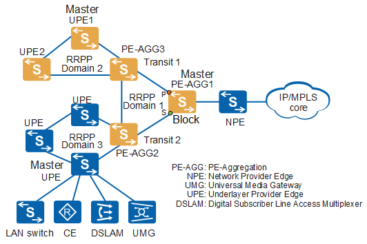
Two tangent rings cannot belong to the same RRPP domain. The tangent point of the two tangent rings belongs to two RRPP domains, and the major node can be located in the tangent point.
When there are multiple tangent RRPP rings, a fault on a ring does not affect other domains and the convergence process of RRPP rings in a domain is the same as that of a single ring.
Configuration Notes
- STP and Smart Link must be disabled on the interface added to an RRPP domain.
- DHCP and MAC address limiting rules cannot be configured in an RRPP control VLAN.
- When the mapping between the protected instance and MUX VLAN needs to be configured, you are advised to configure the principal VLAN, subordinate group VLAN, and subordinate separate VLAN in the MUX VLAN in the protected instance. Otherwise, loops may occur.
- This example applies to all versions of all S series switches.
Networking Requirements
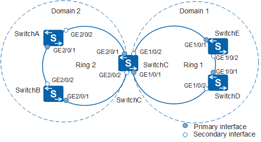
In Figure 1, the network is required to prevent loops when the ring is complete and to implement fast convergence to rapidly restore communication between nodes in the ring when the ring fails. RRPP can meet this requirement. RRPP supports multiple rings. You can configure RRPP rings at the aggregation and access layers. The two rings are tangent, simplifying the network configuration.
SwitchA, SwitchB, SwitchC, SwitchD, and SwitchE in Figure 2 correspond to UPE1, UPE2, PE-AGG3, PE-AGG2, and PE-AGG1 in Figure 1, respectively. Figure 2 is used as an example to describe how to configure tangent RRPP rings with a single instance.
Configuration Roadmap
The configuration roadmap is as follows:
Map the VLANs that need to pass through ring 1 to instance 1, including data VLANs and control VLANs, which are used for configuring protected VLANs.
Map the VLANs that need to pass through ring 2 to instance 2, including data VLANs and control VLANs, which are used for configuring protected VLANs.
Create RRPP domains, control VLANs and configure protected VLANs for configuring RRPP rings.
Configure interfaces to be added to the RRPP domain on the devices so that data can pass through the interfaces. Disable protocols that conflict with RRPP, such as STP.
- Create RRPP rings in RRPP domains.
Configure SwitchA, SwitchB, and SwitchC to be in ring 2 of RRPP domain 2.
Configure SwitchC, SwitchD, and SwitchE to be in ring 1 of RRPP domain 1.
Configure SwitchA as the master node in ring 2, and configure SwitchB and SwitchC as transit nodes in ring 2.
Configure SwitchE as the master node in ring 1, and configure SwitchC and SwitchD as transit nodes in ring 1.
Enable the RRPP ring and RRPP on devices.
Procedure
- Configure instance 2 and map it to the data VLANs and control
VLANs allowed by the RRPP interface.
# Configure SwitchA. The configurations of SwitchB, SwitchC, SwitchD, and SwitchE are similar to the configuration of SwitchA, and are not mentioned here. For details, see the configuration files.
<HUAWEI> system-view
[HUAWEI] sysname SwitchA
[SwitchA] stp region-configuration
[SwitchA-mst-region] instance 2 vlan 20 to 21  ///Add the major control VLAN and sub-control VLAN to instance 1.
[SwitchA-mst-region] active region-configuration
[SwitchA-mst-region] quit
- Create RRPP domains and configure control VLANs and protected
VLANs of the RRPP domains.
# Configure SwitchE. The configurations of SwitchA, SwitchB, SwitchC, and SwitchD are similar to the configuration of SwitchE, and are not mentioned here. For details, see the configuration files.
[SwitchE] rrpp domain 1
[SwitchE-rrpp-domain-region1] control-vlan 10  //Each RRPP domain has a major control VLAN and a sub-control VLAN. You only need to specify the major control VLAN. The system uses the VLAN whose ID is one greater than the ID of the major control VLAN as the sub-control VLAN.
[SwitchE-rrpp-domain-region1] protected-vlan reference-instance 1   //Configure instance 1 as the protected instance of the RRPP domain.
[SwitchE-rrpp-domain-region1] quit
- Configure the interfaces to be added to RRPP rings as trunk
interfaces and disable STP on the interfaces.
# Configure SwitchA. The configurations of SwitchB, SwitchC, SwitchD, and SwitchE are similar to the configuration of SwitchA, and are not mentioned here. For details, see the configuration files.
[SwitchA] interface gigabitethernet 2/0/1
[SwitchA-GigabitEthernet2/0/1] port link-type trunk
[SwitchA-GigabitEthernet2/0/1] undo port trunk allow-pass vlan 1
[SwitchA-GigabitEthernet2/0/1] stp disable
[SwitchA-GigabitEthernet2/0/1] quit
[SwitchA] interface gigabitethernet 2/0/2
[SwitchA-GigabitEthernet2/0/2] port link-type trunk
[SwitchA-GigabitEthernet2/0/2] undo port trunk allow-pass vlan 1
[SwitchA-GigabitEthernet2/0/2] stp disable
[SwitchA-GigabitEthernet2/0/2] quit
- Create and enable the RRPP ring.
Configure nodes in ring 2.
# Configure SwitchA as the master node in ring 2 and specify the primary and secondary interfaces.
[SwitchA] rrpp domain 2
[SwitchA-rrpp-domain-region2] ring 2 node-mode master primary-port gigabitethernet 2/0/1 secondary-port gigabitethernet 2/0/2 level 0
[SwitchA-rrpp-domain-region2] ring 2 enable
[SwitchA-rrpp-domain-region2] quit
# Configure SwitchB as a transit node in ring 2 (major ring) and specify the primary and secondary interfaces.
[SwitchB] rrpp domain 2
[SwitchB-rrpp-domain-region2] ring 2 node-mode transit primary-port gigabitethernet 2/0/1 secondary-port gigabitethernet 2/0/2 level 0
[SwitchB-rrpp-domain-region2] ring 2 enable
[SwitchB-rrpp-domain-region2] quit
# Configure SwitchC as a transit node in ring 2 and specify the primary and secondary interfaces.
[SwitchC] rrpp domain 2
[SwitchC-rrpp-domain-region2] ring 2 node-mode transit primary-port gigabitethernet 2/0/1 secondary-port gigabitethernet 2/0/2 level 0
[SwitchC-rrpp-domain-region2] ring 2 enable
[SwitchC-rrpp-domain-region2] quit
Configure nodes in ring 1.
# Configure SwitchE as the master node in ring 1 (major ring) and specify the primary and secondary interfaces.
[SwitchE] rrpp domain 1
[SwitchE-rrpp-domain-region1] ring 1 node-mode master primary-port gigabitethernet 1/0/1 secondary-port gigabitethernet 1/0/2 level 0
[SwitchE-rrpp-domain-region1] ring 1 enable
[SwitchE-rrpp-domain-region1] quit
# Configure SwitchC as a transit node in ring 1 and specify the primary and secondary interfaces.
[SwitchC] rrpp domain 1
[SwitchC-rrpp-domain-region1] ring 1 node-mode transit primary-port gigabitethernet 1/0/1 secondary-port gigabitethernet 1/0/2 level 0
[SwitchC-rrpp-domain-region1] ring 1 enable
[SwitchC-rrpp-domain-region1] quit
# Configure SwitchD as a transit node in ring 1 and specify the primary and secondary interfaces.
[SwitchD] rrpp domain 1
[SwitchD-rrpp-domain-region1] ring 1 node-mode transit primary-port gigabitethernet 1/0/1 secondary-port gigabitethernet 1/0/2 level 0
[SwitchD-rrpp-domain-region1] ring 1 enable
[SwitchD-rrpp-domain-region1] quit
- Enable RRPP.
# Configure SwitchA. The configurations of SwitchB, SwitchC, SwitchD, and SwitchE are similar to the configuration of SwitchA, and are not mentioned here. For details, see the configuration files.
[SwitchA] rrpp enable - Verify the configuration.
After the configuration is complete and the network topology becomes stable, perform the following operations to verify the configuration. The tangent point SwitchC is used as an example.
# Run the display rrpp brief command on SwitchC. The following information is displayed:
[SwitchC] display rrpp brief
Abbreviations for Switch Node Mode :
M - Master , T - Transit , E - Edge , A - Assistant-Edge

RRPP Protocol Status:  Enable
RRPP Working Mode: HW
RRPP Linkup Delay Timer: 0 sec (0 sec default)
Number of RRPP Domains: 2

Domain Index   : 1
Control VLAN   : major 10    sub 11
Protected VLAN : Reference Instance 1
Hello Timer    : 1 sec(default is 1 sec)  Fail Timer : 6 sec(default is 6 sec)
 Ring   Ring    Node     Primary/Common           Secondary/Edge          Is
 ID     Level   Mode     Port                     Port                    Enabled
 ----------------------------------------------------------------------------
 1      0       T        GigabitEthernet1/0/1     GigabitEthernet1/0/2    Yes

Domain Index   : 2
Control VLAN   : major 20    sub 21
Protected VLAN : Reference Instance 2
Hello Timer    : 1 sec(default is 1 sec)  Fail Timer : 6 sec(default is 6 sec)
 Ring   Ring    Node     Primary/Common           Secondary/Edge          Is
 ID     Level   Mode     Port                     Port                    Enabled
 ----------------------------------------------------------------------------
 2      0       T        GigabitEthernet2/0/1     GigabitEthernet2/0/2    Yes
According to the preceding information, RRPP is enabled on SwitchC. The major control VLAN of RRPP domain 1 is VLAN 10 and the sub-control VLAN is VLAN 11. SwitchC is a transit node in ring 1. The primary interface is GigabitEthernet1/0/1 and the secondary interface is GigabitEthernet1/0/2.
The major control VLAN of SwitchC in RRPP domain 2 is VLAN 20 and the sub-control VLAN is VLAN 21. SwitchC is a transit node in ring 2. The primary interface is GigabitEthernet2/0/1 and the secondary interface is GigabitEthernet2/0/2.
On SwitchC, run the display rrpp verbose domain command. The following information is displayed.
# Check detailed information about RRPP domain 1 on SwitchC.
[SwitchC] display rrpp verbose domain 1
Domain Index  : 1
Control VLAN   : major 10    sub 11
Protected VLAN : Reference Instance 1
Hello Timer    : 1 sec(default is 1 sec)  Fail Timer : 6 sec(default is 6 sec)

RRPP Ring      : 1
Ring Level     : 0
Node Mode      : Transit
Ring State     : LinkUp
Is Enabled     : Enable                       Is Active: Yes
Primary port   : GigabitEthernet1/0/1         Port status: UP
Secondary port : GigabitEthernet1/0/2         Port status: UP
# Check detailed information about RRPP domain 2 on SwitchC.
[SwitchC] display rrpp verbose domain 2
Domain Index   : 2
Control VLAN   : major 20    sub 21
Protected VLAN : Reference Instance 2
Hello Timer    : 1 sec(default is 1 sec)  Fail Timer : 6 sec(default is 6 sec)

RRPP Ring      : 2
Ring Level     : 0
Node Mode      : Transit
Ring State     : LinkUp
Is Enabled     : Enable                       Is Active: Yes
Primary port   : GigabitEthernet2/0/1         Port status: UP
Secondary port : GigabitEthernet2/0/2         Port status: UP
Configuration Files
SwitchA configuration file
#
sysname SwitchA
#
vlan batch 20 to 21
#
rrpp enable
#
stp region-configuration
 instance 2 vlan 20 to 21
 active region-configuration
#
rrpp domain 2
 control-vlan 20
 protected-vlan reference-instance 2
 ring 2 node-mode master primary-port GigabitEthernet2/0/1 secondary-port GigabitEthernet2/0/2 level 0
 ring 2 enable
#
interface GigabitEthernet2/0/1
 port link-type trunk
 undo port trunk allow-pass vlan 1
 port trunk allow-pass vlan 20 to 21
 stp disable
#
interface GigabitEthernet2/0/2
 port link-type trunk
 undo port trunk allow-pass vlan 1
 port trunk allow-pass vlan 20 to 21
 stp disable
#
return
SwitchB configuration file
#
sysname SwitchB
#
vlan batch 20 to 21
#
rrpp enable
#
stp region-configuration
 instance 2 vlan 20 to 21
 active region-configuration
#
rrpp domain 2
 control-vlan 20
 protected-vlan reference-instance 2
 ring 2 node-mode transit primary-port GigabitEthernet2/0/1 secondary-port GigabitEthernet2/0/2 level 0
 ring 2 enable
#
interface GigabitEthernet2/0/1
 port link-type trunk
 undo port trunk allow-pass vlan 1
 port trunk allow-pass vlan 20 to 21
 stp disable
#
interface GigabitEthernet2/0/2
 port link-type trunk
 undo port trunk allow-pass vlan 1
 port trunk allow-pass vlan 20 to 21
 stp disable
#
return
SwitchC configuration file
#
sysname SwitchC
#
vlan batch 10 to 11 20 to 21
#
rrpp enable
#
stp region-configuration
 instance 1 vlan 10 to 11
 instance 2 vlan 20 to 21
 active region-configuration
#
rrpp domain 1
 control-vlan 10
 protected-vlan reference-instance 1
 ring 1 node-mode transit primary-port GigabitEthernet1/0/1 secondary-port GigabitEthernet1/0/2 level 0
 ring 1 enable
rrpp domain 2
 control-vlan 20
 protected-vlan reference-instance 2
 ring 2 node-mode transit primary-port GigabitEthernet2/0/1 secondary-port GigabitEthernet2/0/2 level 0
 ring 2 enable
#
interface GigabitEthernet1/0/1
 port link-type trunk
 undo port trunk allow-pass vlan 1
 port trunk allow-pass vlan 10 to 11
 stp disable
#
interface GigabitEthernet1/0/2
 port link-type trunk
 undo port trunk allow-pass vlan 1
 port trunk allow-pass vlan 10 to 11
 stp disable
#
interface GigabitEthernet2/0/1
 port link-type trunk
 undo port trunk allow-pass vlan 1
 port trunk allow-pass vlan 20 to 21
 stp disable
#
interface GigabitEthernet2/0/2
 port link-type trunk
 undo port trunk allow-pass vlan 1
 port trunk allow-pass vlan 20 to 21
 stp disable
#
return
SwitchD configuration file
#
sysname SwitchD
#
vlan batch 10 to 11
#
rrpp enable
#
stp region-configuration
 instance 1 vlan 10 to 11
 active region-configuration
#
rrpp domain 1
 control-vlan 10
 protected-vlan reference-instance 1
 ring 1 node-mode transit primary-port GigabitEthernet1/0/1 secondary-port GigabitEthernet1/0/2 level 0
 ring 1 enable
#
interface GigabitEthernet1/0/1
 port link-type trunk
 undo port trunk allow-pass vlan 1
 port trunk allow-pass vlan 10 to 11
 stp disable
#
interface GigabitEthernet1/0/2
 port link-type trunk
 undo port trunk allow-pass vlan 1
 port trunk allow-pass vlan 10 to 11
 stp disable
#
return
SwitchE configuration file
#
sysname SwitchE
#
vlan batch 10 to 11
#
rrpp enable
#
stp region-configuration
 instance 1 vlan 10 to 11
 active region-configuration
#
rrpp domain 1
 control-vlan 10
 protected-vlan reference-instance 1
 ring 1 node-mode master primary-port GigabitEthernet1/0/1 secondary-port GigabitEthernet1/0/2 level 0
 ring 1 enable
#
interface GigabitEthernet1/0/1
 port link-type trunk
 undo port trunk allow-pass vlan 1
 port trunk allow-pass vlan 10 to 11
 stp disable
#
interface GigabitEthernet1/0/2
 port link-type trunk
 undo port trunk allow-pass vlan 1
 port trunk allow-pass vlan 10 to 11
 stp disable
#
return