Example for Configuring EFM for IPv4 Static Routes
Overview of EFM for IPv4 Static Routes
Ethernet in the first mile (EFM) defines the specifications of the Ethernet physical layer for user access and implements Ethernet management and maintenance. EFM provides link-level operation and management (OAM), for example, link connectivity detection, link fault monitoring, remote fault notification, and remote loopback functions on a link between two directly-connected devices.
Static routes are easy to configure and therefore widely used on networks with simple structures. Unlike dynamic routing protocols, static routes do not have a dedicated detection mechanism. If a fault occurs, static routes cannot detect the fault, and the network administrator must delete the corresponding static route. This delays the link switchover and may cause lengthy service interruptions. IP networks are being used more often to carry multiple services such as voice and video services. These services pose high requirements on network reliability, and fast fault detection and processing. EFM for IPv4 static routes can be configured to provide the detection mechanism for static routes so that they can detect the link quality changes in real time and switch services immediately.
Configuration Notes
- By default, EFM is disabled globally and on interfaces.
- After EFM OAM is enabled on an interface, the interface starts to send OAM PDUs to perform the point-to-point EFM link detection. EFM link detection can be implemented between two interfaces only after EFM OAM is enabled on the peer interface.
- Applicable products and versions: switches of all models.
Networking Requirements
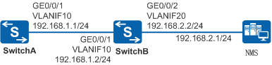
As shown in Figure 1, SwitchA connects to the NMS across a network segment through SwitchB. SwitchA and SwitchB need to detect the link quality in real time. When the link between them becomes faulty, the corresponding static route is deleted from the IP routing table. Then traffic switches from the faulty link to a normal route to improve network reliability.
Configuration Roadmap
The configuration roadmap is as follows:
Enable EFM OAM globally and on interfaces of SwitchA and SwitchB to implement real-time link quality detection.
Configure a static route from SwitchA to the NMS and bind it to the EFM state to associate the static route with EFM. When a link where the static route resides becomes faulty, traffic switches to a route without link faults.
Procedure
- Specify the VLAN to which the interfaces belong.
# Configure SwitchA. The configuration of SwitchB is similar.
<HUAWEI> system-view
[HUAWEI] sysname SwitchA
[SwitchA] vlan 10
[SwitchA-vlan10] quit
[SwitchA] interface gigabitethernet 0/0/1
[SwitchA-GigabitEthernet0/0/1] port link-type trunk
[SwitchA-GigabitEthernet0/0/1] port trunk allow-pass vlan 10
[SwitchA-GigabitEthernet0/0/1] quit
- Configure an IP address for each VLANIF interface.
# Configure SwitchA. The configuration of SwitchB is similar.
[SwitchA] interface vlanif 10
[SwitchA-Vlanif10] ip address 192.168.1.1 24
[SwitchA-Vlanif10] quit
- Configure an EFM session between SwitchA and SwitchB.
# Enable EFM OAM on SwitchA.
[SwitchA] efm enable   //Enable EFM globally.
[SwitchA] interface gigabitethernet 0/0/1
[SwitchA-GigabitEthernet0/0/1] efm enable   //Enable EFM on an interface.
[SwitchA-GigabitEthernet0/0/1] quit
# Enable EFM OAM on SwitchB.
[SwitchB] efm enable   //Enable EFM globally.
[SwitchB] interface gigabitethernet 0/0/1
[SwitchB-GigabitEthernet0/0/1] efm enable   //Enable EFM on an interface.
[SwitchB-GigabitEthernet0/0/1] quit
- Configure a static route and bind it to the EFM state.
# Configure a static route from SwitchA to the external network and bind it to the EFM state of GigabitEthernet0/0/1.
[SwitchA] ip route-static 192.168.2.0 24 192.168.1.2 track efm-state gigabitethernet0/0/1
- Verify the configuration.
# After the configuration is complete, run the display efm session all command on SwitchA and SwitchB. The command output shows that an EFM session has been set up and in detect mode. That is, the interface is in handshake state. The following uses the display on SwitchA as an example.
[SwitchA] display efm session all
  Interface                 EFM State                   Loopback Timeout
  ----------------------------------------------------------------------
  GigabitEthernet0/0/1      detect                      --
# Check the IP routing table on SwitchA. The IP routing table contains the static route.
[SwitchA] display ip routing-table
Route Flags: R - relay, D - download to fib, T - to vpn-instance
------------------------------------------------------------------------------
Routing Tables: Public
         Destinations : 5       Routes : 5

Destination/Mask    Proto   Pre  Cost      Flags NextHop         Interface

      127.0.0.0/8   Direct  0    0           D   127.0.0.1       InLoopBack0
      127.0.0.1/32  Direct  0    0           D   127.0.0.1       InLoopBack0
    192.168.1.0/24  Direct  0    0           D   192.168.1.1     Vlanif10
    192.168.1.1/32  Direct  0    0           D   127.0.0.1       Vlanif10
    192.168.2.0/24  Static  60   0          RD   192.168.1.2     Vlanif10
# Run the undo efm enable command in the view of GigabitEthernet0/0/1 on SwitchB to simulate a link fault.
[SwitchB] interface gigabitethernet 0/0/1
[SwitchB-GigabitEthernet0/0/1] undo efm enable
# Run the display efm session all command on SwitchA. The command output shows that the EFM OAM protocol state is discovery, indicating that the interface is in OAM discovery state.
[SwitchA] display efm session all
  Interface                 EFM State                   Loopback Timeout
  ----------------------------------------------------------------------
  GigabitEthernet0/0/1      discovery                   --
# Check the IP routing table on SwitchA. The IP routing table does not contain the static route 192.168.2.0/24. This is because the static route is bound to the EFM state. After EFM OAM detects a link fault, it rapidly notifies SwitchA that the static route is unavailable.
[SwitchA] display ip routing-table
Route Flags: R - relay, D - download to fib, T - to vpn-instance
------------------------------------------------------------------------------
Routing Tables: Public
         Destinations : 4       Routes : 4

Destination/Mask    Proto   Pre  Cost      Flags NextHop         Interface

      127.0.0.0/8   Direct  0    0           D   127.0.0.1       InLoopBack0
      127.0.0.1/32  Direct  0    0           D   127.0.0.1       InLoopBack0
    192.168.1.0/24  Direct  0    0           D   192.168.1.1     Vlanif10
    192.168.1.1/32  Direct  0    0           D   127.0.0.1       Vlanif10
# Run the efm enable command in the view of GigabitEthernet0/0/1 on SwitchB to simulate link recovery.
[SwitchB-GigabitEthernet0/0/1]efm enable
# Run the display efm session all command on SwitchA. The command output shows that the EFM OAM protocol state is detect, indicating that the interface is in handshake state again.
[SwitchA] display efm session all
  Interface                 EFM State                   Loopback Timeout
  ----------------------------------------------------------------------
  GigabitEthernet0/0/1      detect                      --
# Check the IP routing table on SwitchA. The IP routing table contains the static route 192.168.2.0/24 again. After EFM OAM detects that the link recovers from a fault, it rapidly notifies that the bound static route is valid again.
[SwitchA] display ip routing-table
Route Flags: R - relay, D - download to fib, T - to vpn-instance
------------------------------------------------------------------------------
Routing Tables: Public
         Destinations : 5       Routes : 5

Destination/Mask    Proto   Pre  Cost      Flags NextHop         Interface

      127.0.0.0/8   Direct  0    0           D   127.0.0.1       InLoopBack0
      127.0.0.1/32  Direct  0    0           D   127.0.0.1       InLoopBack0
    192.168.1.0/24  Direct  0    0           D   192.168.1.1     Vlanif10
    192.168.1.1/32  Direct  0    0           D   127.0.0.1       Vlanif10
    192.168.2.0/24  Static  60   0          RD   192.168.1.2     Vlanif10
Configuration Files
SwitchA configuration file
#
sysname SwitchA
#
vlan batch 10
#
efm enable
#
interface Vlanif10
 ip address 192.168.1.1 255.255.255.0
#
interface GigabitEthernet0/0/1
 port link-type trunk
 port trunk allow-pass vlan 10
 efm enable
#
ip route-static 192.168.2.0 255.255.255.0 192.168.1.2 track efm-state GigabitEthernet0/0/1
#
return
SwitchB configuration file
#
sysname SwitchB
#
vlan batch 10 20
#
efm enable
#
interface Vlanif10
 ip address 192.168.1.2 255.255.255.0
#
interface Vlanif20
 ip address 192.168.2.2 255.255.255.0
#
interface GigabitEthernet0/0/1
 port link-type trunk
 port trunk allow-pass vlan 10
 efm enable
#
interface GigabitEthernet0/0/2
 port link-type trunk
 port trunk allow-pass vlan 20
#
return