Planning SVF System Networking
An SVF system supports at most two levels of ASs and one level of APs. Before setting up an SVF system, determine the SVF application scenario and select the required networking based on deployment restrictions, reliability, and system CPU consumption.
Determining Campus Network Scenarios
When determining campus network scenarios, consider factors such as the terminal quantity, terminal type, whether to reuse existing devices, and CPU/memory capabilities of the parent.
- Calculate the number of required ASs based on the number of wired terminals.
- Calculate the number of required APs based on the number of wireless terminals.
- Determine whether to reuse existing devices. These devices can be reused to transparently transmit packets between the parent and ASs. It is not recommended to connect users to these existing devices, as doing so may cause a failure to set up an SVF system.
An SVF system is configured and maintained on the parent. If more ASs&APs are deployed, more terminals can connect to the campus network, requiring more CPU and memory resources of the parent. Table 1 lists the recommended maximum numbers of ASs&APs and access terminals in an SVF system depending on CPU and memory capabilities of the parent. If the number of access terminals exceeds the recommended value, you are advised to divide the campus network into multiple SVF systems according to Scenario 3: Campus Network of Multiple SVF Systems.
Table 1 Recommended maximum numbers of ASs&APs and access terminals Model of the Parent
Recommended Maximum Number of ASs
Recommended Maximum Number of APs
S12712, S12710, S12708, S12704, S12700E-4, S12700E-8, S12700E-12
256
1000
S9712, S9706
48
800
- S7703 and S7703 PoE: with MCUD
- S7706, S7706 PoE, and S7712: with SRUE, SRUHA1, SRUHX1, or SRUH
256
1000
S7706, S7706 PoE, and S7712: with SRUA or SRUB
32
300
- S9303: with MCUD
- S9306 and S9312: with SRUE, SRUHA1, SRUHX1, or SRUH
- S9310
256
0
S9306 and S9312: with SRUA or SRUB
32
0
S5720-HI
32
600
S5730-HI, S5731-H, S5731S-H, S5732-H, S6720-HI, S6730-H, S6730S-H
32
600
- S7703 and S7703 PoE: with MCUA
- S9703
4
0
S9303: with MCUA
4
0
S6720-EI, S6720S-EI, S6730-S, S6730S-S
32
0
- Select the required networking scenario. Table 2 lists the recommended scenarios.
Table 2 Recommended networking scenarios Number of Terminals
Terminal Type
Recommended Networking Scenario
The number of terminals does not exceed the recommended value on the parent.
Only wired terminals exist, and no existing devices need to be reused.
Scenario 1: Networking in which the parent and ASs are directly connected on a wired campus network
Only wired terminals exist, and existing devices need to be reused.
Both wired and wireless terminals exist, and no existing devices need to be reused.
Both wired and wireless terminals exist, and existing devices need to be reused.
The number of terminals exceeds the recommended value on the parent.
During system planning, you are advised to divide the campus network into multiple SVF systems. Scenario 3: Campus Network of Multiple SVF Systems shows networking scenarios. In each SVF system, ensure that the number of terminals does not exceed the recommended value on the parent, and select the recommended scenario according to the terminal type.
Networking deployment recommendations
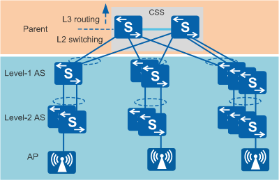
Figure 1 shows an ideal SVF networking. It has the following characteristics:
- The parent is a CSS of two member devices.
- Each Level-1 AS is dual-homed to two member devices of the parent through uplink ports.
- When an AS is a stack of multiple member devices, each member device is connected to its upstream device through at least one link.
- ASs are connected to upstream devices through uplink optical ports or uplink combo ports.
- APs are single-homed to ASs.
This SVF networking has the following advantages:
- A failure of a single link between two devices affects only the bandwidth but not services.
- An AS performs multi-active detection (MAD), and its upstream device functions as the MAD relay agent. When the AS splits as a stack, it can work with the upstream device to perform MAD without affecting the system stability.
Implementing the ideal SVF networking may fail because of restrictions such as the distance between devices and cabling difficulties. You need to identify these networking restrictions in advance and take appropriate measures. The following provides suggestions on SVF deployment in different situations:
- If the parent is a standalone device:
- Deploy two MPUs on the parent to ensure reliability.
- Connect each AS to the parent using at least two links and ensure that the links are connected to at least two different LPUs of the parent.
- If a level-1 AS cannot be dual-homed to the parent:
- Use a standalone device as a level-1 AS. If the AS needs to be a stack, deploy member devices in the same physical location and ensure stack cable reliability. Otherwise, device conflicts cannot be resolved after the stack splits, affecting system reliability.
- If the AS is a stack of multiple member devices and you cannot ensure that each member device connects to its upstream device through at least one link:
- Deploy member devices in the same physical location and ensure stack cable reliability. Otherwise, device conflicts cannot be resolved after the stack splits, affecting system reliability.
- If member ports of the fabric port that connects an AS to an upstream device can only be connected through twisted pairs:
- Use copper modules to convert the optical/electrical attributes of ports when uplink ports of ASs are GE ports.
- Select ASs that have uplink combo ports, for example, some S2750-EI models.
Improving System Reliability
- Improve reliability of the parent using the following methods:
- Set up a CSS of two member devices for the parent.
- Deploy MAD to take recovery actions when the CSS splits.
- Improve reliability of an AS using the following methods:
- If the parent is a CSS of two member devices, dual-home the level-1 AS to two member devices of the parent.
- If the AS is a stack of multiple member devices, ensure that each member device is connected to its upstream device through at least one link.
- If the AS is a stack of multiple member devices, set up the stack in ring topology.
- If the AS is a stack of multiple member devices, deploy all the member devices in the same physical location to reduce the risk of a stack split caused by link failures.