Example for Configuring Routing Policies to Control Mutual Access Between L3VPN Users
Overview
BGP/MPLS IP VPN is an MPLS-based L3VPN that can be flexibly deployed and easily extended, and is suitable for deployment on a large scale. BGP/MPLS IP VPN technology can be used to implement secure communication or isolation between branches in different locations.
Routing policies are used to filter routes and set route attributes. You can change route attributes to change a route over which network traffic is transmitted.
BGP/MPLS IP VPN can be combined with routing policies to control the receiving and advertisement of VPN routes, implementing mutual access between specific branch users.
Configuration Notes
- The SA series cards do not support the BGP/MPLS IP VPN function. The X1E series cards of V200R006C00 and later versions support the BGP/MPLS IP VPN function.
- Applicable products and versions lists applicable products and versions.

For details about software mappings, visit Hardware Query Tool and search for the desired product model.
Networking Requirements
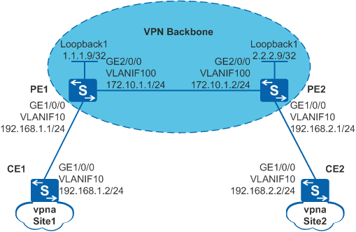
As shown in Figure 1, CE1 is connected to the branch Site 1, and CE2 is connected to the branch Site 2. Site 1 and Site 2 communicate with each other over the ISP backbone network. The enterprise requires that L3VPN users on some network segments can securely communicate with each other to meet service requirements.
Configuration Roadmap
The configuration roadmap is as follows:
- Configure OSPF between the PE devices to ensure IP connectivity on the backbone network.
- Enable basic MPLS capabilities and MPLS LDP on the PE devices to set up MPLS LSP tunnels for VPN data transmission on the backbone network.
- Create VPN instances on the PE devices, bind CE interfaces to the VPN instances, and assign different VPN targets to the VPN instances to isolate users from different branches.
- Configure routing policies on the PE devices and change the VPN targets of routes filtered out based on specified routing policies to implement communication between branch users on a specified network segment.
- Set up EBGP peer relationships between the CE and PE devices so that they can exchange VPN routing information.
- Configure MP-IBGP between the PE devices to enable them to exchange VPN routing information.
Procedure
- Configure an IGP protocol on the MPLS backbone network so that the PE devices can communicate with each other.
# Configure PE1.
<HUAWEI> system-view
[HUAWEI] sysname PE1
[PE1] interface loopback 1
[PE1-LoopBack1] ip address 1.1.1.9 32
[PE1-LoopBack1] quit
[PE1] vlan batch 10 100
[PE1] interface gigabitethernet 1/0/0
[PE1-GigabitEthernet1/0/0] port link-type trunk
[PE1-GigabitEthernet1/0/0] port trunk allow-pass vlan 10
[PE1-GigabitEthernet1/0/0] quit
[PE1] interface gigabitethernet 2/0/0
[PE1-GigabitEthernet2/0/0] port link-type trunk
[PE1-GigabitEthernet2/0/0] port trunk allow-pass vlan 100
[PE1-GigabitEthernet2/0/0] quit
[PE1] interface vlanif 100
[PE1-Vlanif100] ip address 172.10.1.1 24
[PE1-Vlanif100] quit
[PE1] ospf 1
[PE1-ospf-1] area 0
[PE1-ospf-1-area-0.0.0.0] network 172.10.1.0 0.0.0.255
[PE1-ospf-1-area-0.0.0.0] network 1.1.1.9 0.0.0.0
[PE1-ospf-1-area-0.0.0.0] quit
[PE1-ospf-1] quit
# Configure PE2.
<HUAWEI> system-view
[HUAWEI] sysname PE2
[PE2] interface loopback 1
[PE2-LoopBack1] ip address 2.2.2.9 32
[PE2-LoopBack1] quit
[PE2] vlan batch 10 100
[PE2] interface gigabitethernet 1/0/0
[PE2-GigabitEthernet1/0/0] port link-type trunk
[PE2-GigabitEthernet1/0/0] port trunk allow-pass vlan 10
[PE2-GigabitEthernet1/0/0] quit
[PE2] interface gigabitethernet 2/0/0
[PE2-GigabitEthernet2/0/0] port link-type trunk
[PE2-GigabitEthernet2/0/0] port trunk allow-pass vlan 100
[PE2-GigabitEthernet2/0/0] quit
[PE2] interface vlanif 100
[PE2-Vlanif100] ip address 172.10.1.2 24
[PE2-Vlanif100] quit
[PE2] ospf 1
[PE2-ospf-1] area 0
[PE2-ospf-1-area-0.0.0.0] network 172.10.1.0 0.0.0.255
[PE2-ospf-1-area-0.0.0.0] network 2.2.2.9 0.0.0.0
[PE2-ospf-1-area-0.0.0.0] quit
[PE2-ospf-1] quit
After the configuration is complete, run the display ospf peer command. The command output shows that OSPF neighbor relationship has been set up between PE1 and PE2, and the neighbor status is Full. Run the display ip routing-table command on PE1 and PE2, and you can view that PE1 and PE2 have learned the routes to each other's Loopback1 address.
- Enable basic MPLS capabilities and MPLS LDP on the PE devices to set up LDP LSPs on the MPLS backbone network.
# Configure PE1.
[PE1] mpls lsr-id 1.1.1.9
[PE1] mpls
[PE1-mpls] quit
[PE1] mpls ldp
[PE1-mpls-ldp] quit
[PE1] interface vlanif 100
[PE1-Vlanif100] mpls
[PE1-Vlanif100] mpls ldp
[PE1-Vlanif100] quit
# Configure PE2.
[PE2] mpls lsr-id 2.2.2.9
[PE2] mpls
[PE2-mpls] quit
[PE2] mpls ldp
[PE2-mpls-ldp] quit
[PE2] interface vlanif 100
[PE2-Vlanif100] mpls
[PE2-Vlanif100] mpls ldp
[PE2-Vlanif100] quit
After the configuration is complete, PE1 and PE2 have established LDP sessions. Run the display mpls ldp session command, and you can view that the LDP session status is Operational.
- Configure a VPN instance on each PE device and connect the CE devices to the PE devices.
# Configure PE1.
[PE1] ip vpn-instance vpna
[PE1-vpn-instance-vpna] route-distinguisher 100:1
[PE1-vpn-instance-vpna-af-ipv4] vpn-target 111:1 both
[PE1-vpn-instance-vpna-af-ipv4] quit
[PE1-vpn-instance-vpna] quit
[PE1] interface vlanif 10
[PE1-Vlanif10] ip binding vpn-instance vpna
[PE1-Vlanif10] ip address 192.168.1.1 24
[PE1-Vlanif10] quit
# Configure PE2.
[PE2] ip vpn-instance vpna
[PE2-vpn-instance-vpna] route-distinguisher 200:1
[PE2-vpn-instance-vpna-af-ipv4] vpn-target 222:1 both
[PE2-vpn-instance-vpna-af-ipv4] quit
[PE2-vpn-instance-vpna] quit
[PE2] interface vlanif 10
[PE2-Vlanif10] ip binding vpn-instance vpna
[PE2-Vlanif10] ip address 192.168.2.1 24
[PE2-Vlanif10] quit
# Assign IP addresses to interfaces on CE1 and CE2 according to Figure 1.
<HUAWEI> system-view
[HUAWEI] sysname CE1
[CE1] vlan batch 10
[CE1] interface gigabitethernet 1/0/0
[CE1-GigabitEthernet1/0/0] port link-type trunk
[CE1-GigabitEthernet1/0/0] port trunk allow-pass vlan 10
[CE1-GigabitEthernet1/0/0] quit
[CE1] interface vlanif 10
[CE1-Vlanif10] ip address 192.168.1.2 24
[CE1-Vlanif10] quit
<HUAWEI> system-view
[HUAWEI] sysname CE2
[CE2] vlan batch 10
[CE2] interface gigabitethernet 1/0/0
[CE2-GigabitEthernet1/0/0] port link-type trunk
[CE2-GigabitEthernet1/0/0] port trunk allow-pass vlan 10
[CE2-GigabitEthernet1/0/0] quit
[CE2] interface vlanif 10
[CE2-Vlanif10] ip address 192.168.2.2 24
[CE2-Vlanif10] quit
After the configuration is complete, run the display ip vpn-instance verbose command on PE1 and PE2 to view VPN instance configuration. The PE devices can ping CE devices attached to them.
If a PE device has multiple interfaces bound to the same VPN instance, you need to specify a source IP address when pinging the CE device connected to the remote PE device. To specify the source IP address, set the -a source-ip-address parameter in the ping -vpn-instance vpn-instance-name -a source-ip-address dest-ip-address command. If no source IP address is specified, the ping operation fails.
- Configure routing policies.
# Configure PE1.
[PE1] ip ip-prefix ipPrefix1 index 10 permit 192.168.1.0 24 greater-equal 24 less-equal 32
[PE1] route-policy vpnroute permit node 1
[PE1-route-policy] if-match ip-prefix ipPrefix1
[PE1-route-policy] apply extcommunity rt 222:1
[PE1-route-policy] quit
[PE1] ip vpn-instance vpna
[PE1-vpn-instance-vpna] export route-policy vpnroute
[PE1-vpn-instance-vpna] quit
# Configure PE2.
[PE2] ip ip-prefix ipPrefix1 index 10 permit 192.168.2.0 24 greater-equal 24 less-equal 32
[PE2] route-policy vpnroute permit node 1
[PE2-route-policy] if-match ip-prefix ipPrefix1
[PE2-route-policy] apply extcommunity rt 111:1
[PE2-route-policy] quit
[PE2] ip vpn-instance vpna
[PE2-vpn-instance-vpna] export route-policy vpnroute
[PE2-vpn-instance-vpna] quit
- Set up EBGP peer relationships between the PE and CE devices and import VPN routes.
# Configure CE1. The configuration of CE2 is similar to that of CE1, and is not mentioned here.
[CE1] bgp 65410
[CE1-bgp] peer 192.168.1.1 as-number 100
[CE1-bgp] import-route direct
[CE1-bgp] quit
# Configure PE1. The configuration of PE2 is similar to that of PE1, and is not mentioned here.
[PE1] bgp 100
[PE1-bgp] ipv4-family vpn-instance vpna
[PE1-bgp-vpna] peer 192.168.1.2 as-number 65410
[PE1-bgp-vpna] import-route direct
[PE1-bgp-vpna] quit
[PE1-bgp] quit
After the configuration is complete, run the display bgp vpnv4 vpn-instance vpna peer command on PE1 and PE2. You can view that BGP peer relationships between PE and CE devices have been established and are in the Established state.
- Set up an MP-IBGP peer relationship between PE1 and PE2.
# Configure PE1.
[PE1] bgp 100
[PE1-bgp] peer 2.2.2.9 as-number 100
[PE1-bgp] peer 2.2.2.9 connect-interface loopback 1
[PE1-bgp] ipv4-family vpnv4
[PE1-bgp-af-vpnv4] peer 2.2.2.9 enable
[PE1-bgp-af-vpnv4] quit
[PE1-bgp] quit
# Configure PE2.
[PE2] bgp 100
[PE2-bgp] peer 1.1.1.9 as-number 100
[PE2-bgp] peer 1.1.1.9 connect-interface loopback 1
[PE2-bgp] ipv4-family vpnv4
[PE2-bgp-af-vpnv4] peer 1.1.1.9 enable
[PE2-bgp-af-vpnv4] quit
[PE2-bgp] quit
After the configuration is complete, run the display bgp peer or display bgp vpnv4 all peer command on PE1 and PE2. You can view that the BGP peer relationships have been established between the PE devices and are in the Established state.
- Verify the configuration.
# Run the ping -vpn-instance command on PE1 and PE2. You can successfully ping the CE site that is attached to the peer PE device.
The display on PE1 is used as an example:
[PE1] ping -vpn-instance vpna 192.168.2.2
  PING 192.168.2.2: 56  data bytes, press CTRL_C to break
    Reply from 192.168.2.2: bytes=56 Sequence=1 ttl=254 time=6 ms
    Reply from 192.168.2.2: bytes=56 Sequence=2 ttl=254 time=5 ms
    Reply from 192.168.2.2: bytes=56 Sequence=3 ttl=254 time=7 ms
    Reply from 192.168.2.2: bytes=56 Sequence=4 ttl=254 time=6 ms
    Reply from 192.168.2.2: bytes=56 Sequence=5 ttl=254 time=5 ms

  --- 192.168.2.2 ping statistics ---
    5 packet(s) transmitted
    5 packet(s) received
    0.00% packet loss
    round-trip min/avg/max = 5/5/7 ms
Configuration Files
Configuration file of PE1
#
sysname PE1
#
vlan batch 10 100
#
ip vpn-instance vpna
 ipv4-family
  route-distinguisher 100:1
  export route-policy vpnroute
  vpn-target 111:1 export-extcommunity
  vpn-target 111:1 import-extcommunity
#
mpls lsr-id 1.1.1.9
mpls
#
mpls ldp
#
interface Vlanif10
 ip binding vpn-instance vpna
 ip address 192.168.1.1 255.255.255.0
#
interface Vlanif100
 ip address 172.10.1.1 255.255.255.0
 mpls
 mpls ldp
#
interface GigabitEthernet1/0/0
 port link-type trunk
 port trunk allow-pass vlan 10
#
interface GigabitEthernet2/0/0
 port link-type trunk
 port trunk allow-pass vlan 100
#
interface LoopBack1
 ip address 1.1.1.9 255.255.255.255
#
bgp 100
 peer 2.2.2.9 as-number 100
 peer 2.2.2.9 connect-interface LoopBack1
 #
 ipv4-family unicast
  undo synchronization
  peer 2.2.2.9 enable
 #
 ipv4-family vpnv4
  policy vpn-target
  peer 2.2.2.9 enable
 #
 ipv4-family vpn-instance vpna
  import-route direct
  peer 192.168.1.2 as-number 65410
#
ospf 1
 area 0.0.0.0
  network 1.1.1.9 0.0.0.0
  network 172.10.1.0 0.0.0.255
#
route-policy vpnroute permit node 1
 if-match ip-prefix ipPrefix1
 apply extcommunity rt 222:1
#
ip ip-prefix ipPrefix1 index 10 permit 192.168.1.0 24 greater-equal 24 less-equal 32
#
return
Configuration file of PE2
#
sysname PE2
#
 vlan batch 10 100
#
ip vpn-instance vpna
 ipv4-family
 route-distinguisher 200:1
 export route-policy vpnroute
 vpn-target 222:1 export-extcommunity
 vpn-target 222:1 import-extcommunity
#
mpls lsr-id 2.2.2.9
mpls
#
mpls ldp
#
interface Vlanif10
 ip binding vpn-instance vpna
 ip address 192.168.2.1 255.255.255.0
#
interface Vlanif100
 ip address 172.10.1.2 255.255.255.0
 mpls
 mpls ldp
#
interface GigabitEthernet1/0/0
 port link-type trunk
 port trunk allow-pass vlan 10
#
interface GigabitEthernet2/0/0
 port link-type trunk
 port trunk allow-pass vlan 100
#
interface LoopBack1
 ip address 2.2.2.9 255.255.255.255
#
bgp 100
 peer 1.1.1.9 as-number 100
 peer 1.1.1.9 connect-interface LoopBack1
  #
 ipv4-family unicast
  undo synchronization
  peer 1.1.1.9 enable
  #
 ipv4-family vpnv4
  policy vpn-target
  peer 1.1.1.9 enable
 #
 ipv4-family vpn-instance vpna
  import-route direct
  peer 192.168.2.2 as-number 65420
#
ospf 1
 area 0.0.0.0
  network 2.2.2.9 0.0.0.0
  network 172.10.1.0 0.0.0.255
#
route-policy vpnroute permit node 1
 if-match ip-prefix ipPrefix1
 apply extcommunity rt 111:1
#
ip ip-prefix ipPrefix1 index 10 permit 192.168.2.0 24 greater-equal 24 less-equal 32
#
return
Configuration file of CE1
#
sysname CE1
#
vlan batch 10
#
interface Vlanif10
 ip address 192.168.1.2 255.255.255.0
#
interface GigabitEthernet1/0/0
 port link-type trunk
 port trunk allow-pass vlan 10
#
bgp 65410
 peer 192.168.1.1 as-number 100
 #
 ipv4-family unicast
  undo synchronization
  import-route direct
  peer 192.168.1.1 enable
#
return
Configuration file of CE2
#
sysname CE2
#
vlan batch 10
#
interface Vlanif10
 ip address 192.168.2.2 255.255.255.0
#
interface GigabitEthernet1/0/0
 port link-type trunk
 port trunk allow-pass vlan 10
#
bgp 65420
 peer 192.168.2.1 as-number 100
 #
 ipv4-family unicast
  undo synchronization
  import-route direct
  peer 192.168.2.1 enable
#
return
Applicable products and versions
Product |
Product Model |
Software Version |
|---|---|---|
S5700 |
S5700-HI |
V200R002C00, V200R003C00, V200R005(C00SPC500&C01&C02) |
S5710-EI |
V200R002C00, V200R003C00, V200R005(C00&C02) |
|
S5710-HI |
V200R003C00, V200R005(C00&C02&C03) |
|
S5720-EI |
V200R009C00, V200R010C00, V200R011C00, V200R011C10, V200R012C00, V200R013C00, V200R019C00, V200R019C10 |
|
S5720-HI |
V200R007C10, V200R009C00, V200R010C00, V200R011C00, V200R011C10, V200R012C00, V200R013C00, V200R019C00, V200R019C10 |
|
S5730-HI |
V200R012C00, V200R013C00, V200R019C00, V200R019C10 |
|
S5731-H |
V200R013C02, V200R019C00, V200R019C10 |
|
S5731S-H |
V200R019C00, V200R019C10 |
|
S5732-H |
V200R019C00, V200R019C10 |
|
S6700 |
S6700-EI |
V200R005(C00&C01) |
S6720-EI |
V200R008C00, V200R009C00, V200R010C00, V200R011C00, V200R011C10, V200R012C00, V200R013C00, V200R019C00, V200R019C10 |
|
S6720S-EI |
V200R009C00, V200R010C00, V200R011C00, V200R011C10, V200R012C00, V200R013C00, V200R019C00, V200R019C10 |
|
S6720-HI |
V200R012C00, V200R013C00, V200R019C00, V200R019C10 |
|
S6730-H |
V200R013C02, V200R019C00, V200R019C10 |
|
S6730S-H |
V200R019C10 |
|
S7700 |
S7703, S7706, S7712 |
V200R001(C00&C01), V200R002C00, V200R003C00, V200R005C00, V200R006C00, V200R007C00, V200R008C00, V200R009C00, V200R010C00, V200R011C10, V200R012C00, V200R013C00, V200R013C02, V200R019C00, V200R019C10 |
S7703 PoE |
V200R013C00, V200R019C00, V200R019C10 |
|
S7706 PoE |
V200R013C00, V200R019C00, V200R019C10 |
|
S9700 |
S9703, S9706, S9712 |
V200R001(C00&C01), V200R002C00, V200R003C00, V200R005C00, V200R006C00, V200R007(C00&C10), V200R008C00, V200R009C00, V200R010C00, V200R011C10, V200R012C00, V200R013C00 |