Example for Configuring L3VPN and VRRP
L3VPN and VRRP Overview
L3VPN is suitable for communication between the headquarters and branches in different locations. As communication data needs to traverse the backbone network of the ISP, BGP is used to advertise VPN routes and MPLS is used to forward VPN packets on the backbone network. As different departments of an enterprise need to be isolated, BGP/MPLS IP VPN can implement route isolation, address space isolation, and access isolation between different VPNs.
Generally, all hosts on the same network segment have the same default route with the gateway address as the next hop address. The hosts use the default route to send packets to the gateway and the gateway forwards the packets to other network segments. When the gateway fails, the hosts with the same default route cannot communicate with external networks. Configuring multiple egress gateways is a common method to improve system reliability. However, route selection between the gateways becomes an issue.
VRRP solves the problem. VRRP virtualizes multiple routing devices into a virtual router without changing the networking, and uses the virtual router IP address as the default gateway address to implement gateway backup. When the master in the virtual router fails, VRRP uses a backup to transmit service traffic.
Preemption mode: A backup preempts to be the master when its priority is higher than the master.
Non-preemption mode: As long as the master is working properly, the backup with a higher priority cannot become the master.
Configuration Notes
- Ensure that each device of the same VRRP group is configured with the same VRID.
In V200R003 and earlier versions, VRRP can be configured only on the VLANIF interface.
In V200R005 and later versions, VRRP can be configured on the VLANIF interface and Layer 3 Ethernet interface.
For a modular switch in V200R006 and later versions, VRRP can be configured on the VLANIF interface, Layer 3 Ethernet interface, Dot1q termination sub-interface, and QinQ termination sub-interface.
For a fixed switch in V200R009 and later versions, VRRP can be configured on the VLANIF interface, Layer 3 Ethernet interface, and sub-interface.
- The SA series cards do not support the BGP/MPLS IP VPN function. The X1E series cards of V200R006C00 and later versions support the BGP/MPLS IP VPN function.
- Applicable products and versions lists applicable products and versions.

For details about software mappings, visit Hardware Query Tool and search for the desired product model.
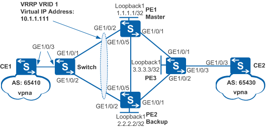
Networking Requirements
Normally, CE1 uses PE1 as the default gateway to communicate with CE2. When PE1 becomes faulty, PE2 takes over PE1, implementing gateway redundancy.
After PE1 recovers, it preempts to be the master to transmit data after a preemption delay of 20s.
In this scenario, to avoid loops, ensure that all connected interfaces have STP disabled and connected interfaces are removed from VLAN 1. If STP is enabled and VLANIF interfaces of switches are used to construct a Layer 3 ring network, an interface on the network will be blocked. As a result, Layer 3 services on the network cannot run normally.
Device |
Interface |
VLANIF Interface |
IP Address |
|---|---|---|---|
PE1 |
GE1/0/1 |
VLANIF 300 |
192.168.1.1/24 |
GE1/0/2 |
VLANIF 100 |
10.1.1.1/24 |
|
GE1/0/5 |
VLANIF 100 |
10.1.1.1/24 |
|
PE2 |
GE1/0/1 |
VLANIF 200 |
192.168.2.1/24 |
GE1/0/2 |
VLANIF 100 |
10.1.1.2/24 |
|
GE1/0/5 |
VLANIF 100 |
10.1.1.2/24 |
|
PE3 |
GE1/0/1 |
VLANIF 300 |
192.168.1.2/24 |
GE1/0/2 |
VLANIF 200 |
192.168.2.2/24 |
|
GE1/0/3 |
VLANIF 400 |
172.16.1.100/24 |
|
CE1 |
GE1/0/3 |
VLANIF 100 |
10.1.1.100/24 |
CE2 |
GE1/0/3 |
VLANIF 400 |
172.16.1.200/24 |
Configuration Roadmap
VRRP is configured to implement gateway redundancy on the L3VPN. The configuration roadmap is as follows:
- Configure OSPF between PEs to implement IP connectivity on the backbone network.
- Configure basic MPLS functions and MPLS LDP on PEs so that MPLS LSPs can be established to transmit VPN data.
- Configure VPN instances on PEs to implement connectivity between VPNs. Bind VPN instances to PE interfaces connected to CEs so that VPN users can be connected.
- Configure MP-IBGP between PE1 and PE3, and between PE2 and PE3 to exchange VPN routing information.
- Configure EBGP between CEs and PEs to exchange VPN routing information.
- Configure a loop prevention protocol on PE1, PE2, and switch to prevent loops. Here, MSTP is used.
- Configure a VRRP group on PE1 and PE2. Set a higher priority for PE1 so that PE1 functions as the master to forward traffic, and set the preemption delay to 20s on PE1. Set a lower priority for PE2 so that PE2 functions as the backup.
Procedure
- Configure an IGP protocol on the MPLS backbone network so that the PEs can communicate with each other.
# Configure PE1.
<HUAWEI> system-view
[HUAWEI] sysname PE1
[PE1] vlan 300
[PE1-vlan300] quit
[PE1] interface gigabitethernet 1/0/1
[PE1-GigabitEthernet1/0/1] port link-type hybrid
[PE1-GigabitEthernet1/0/1] port hybrid pvid vlan 300
[PE1-GigabitEthernet1/0/1] port hybrid untagged vlan 300
[PE1-GigabitEthernet1/0/1] quit
[PE1] interface loopback 1
[PE1-LoopBack1] ip address 1.1.1.1 32
[PE1-LoopBack1] quit
[PE1] interface vlanif 300
[PE1-Vlanif300] ip address 192.168.1.1 24
[PE1-Vlanif300] quit
[PE1] ospf 1
[PE1-ospf-1] area 0
[PE1-ospf-1-area-0.0.0.0] network 192.168.1.0 0.0.0.255
[PE1-ospf-1-area-0.0.0.0] network 1.1.1.1 0.0.0.0
[PE1-ospf-1-area-0.0.0.0] quit
[PE1-ospf-1] quit
# Configure PE2.
<HUAWEI> system-view
[HUAWEI] sysname PE2
[PE2] vlan 200
[PE2-vlan200] quit
[PE2] interface gigabitethernet 1/0/1
[PE2-GigabitEthernet1/0/1] port link-type hybrid
[PE2-GigabitEthernet1/0/1] port hybrid pvid vlan 200
[PE2-GigabitEthernet1/0/1] port hybrid untagged vlan 200
[PE2-GigabitEthernet1/0/1] quit
[PE2] interface loopback 1
[PE2-LoopBack1] ip address 2.2.2.2 32
[PE2-LoopBack1] quit
[PE2] interface vlanif 200
[PE2-Vlanif200] ip address 192.168.2.1 24
[PE2-Vlanif200] quit
[PE2] ospf 1
[PE2-ospf-1] area 0
[PE2-ospf-1-area-0.0.0.0] network 192.168.2.0 0.0.0.255
[PE2-ospf-1-area-0.0.0.0] network 2.2.2.2 0.0.0.0
[PE2-ospf-1-area-0.0.0.0] quit
[PE2-ospf-1] quit
# Configure PE3.
<HUAWEI> system-view
[HUAWEI] sysname PE3
[PE3] vlan batch 200 300
[PE3] interface gigabitethernet 1/0/1
[PE3-GigabitEthernet1/0/1] port link-type hybrid
[PE3-GigabitEthernet1/0/1] port hybrid pvid vlan 300
[PE3-GigabitEthernet1/0/1] port hybrid untagged vlan 300
[PE3-GigabitEthernet1/0/1] quit
[PE3] interface gigabitethernet 1/0/2
[PE3-GigabitEthernet1/0/2] port link-type hybrid
[PE3-GigabitEthernet1/0/2] port hybrid pvid vlan 200
[PE3-GigabitEthernet1/0/2] port hybrid untagged vlan 200
[PE3-GigabitEthernet1/0/2] quit
[PE3] interface loopback 1
[PE3-LoopBack1] ip address 3.3.3.3 32
[PE3-LoopBack1] quit
[PE3] interface vlanif 200
[PE3-Vlanif200] ip address 192.168.2.2 24
[PE3-Vlanif200] quit
[PE3] interface vlanif 300
[PE3-Vlanif300] ip address 192.168.1.2 24
[PE3-Vlanif300] quit
[PE3] ospf 1
[PE3-ospf-1] area 0
[PE3-ospf-1-area-0.0.0.0] network 192.168.2.0 0.0.0.255
[PE3-ospf-1-area-0.0.0.0] network 192.168.1.0 0.0.0.255
[PE3-ospf-1-area-0.0.0.0] network 3.3.3.3 0.0.0.0
[PE3-ospf-1-area-0.0.0.0] quit
[PE3-ospf-1] quit
- Configure basic MPLS functions, enable MPLS LDP, and establish LDP LSPs on the MPLS backbone network.
# Configure PE1.
[PE1] mpls lsr-id 1.1.1.1
[PE1] mpls
[PE1-mpls] quit
[PE1] mpls ldp
[PE1-mpls-ldp] quit
[PE1] interface vlanif 300
[PE1-Vlanif300] mpls
[PE1-Vlanif300] mpls ldp
[PE1-Vlanif300] quit
# Configure PE2.
[PE2] mpls lsr-id 2.2.2.2
[PE2] mpls
[PE2-mpls] quit
[PE2] mpls ldp
[PE2-mpls-ldp] quit
[PE2] interface vlanif 200
[PE2-Vlanif200] mpls
[PE2-Vlanif200] mpls ldp
[PE2-Vlanif200] quit
# Configure PE3.
[PE3] mpls lsr-id 3.3.3.3
[PE3] mpls
[PE3-mpls] quit
[PE3] mpls ldp
[PE3-mpls-ldp] quit
[PE3] interface vlanif 200
[PE3-Vlanif200] mpls
[PE3-Vlanif200] mpls ldp
[PE3-Vlanif200] quit
[PE3] interface vlanif 300
[PE3-Vlanif300] mpls
[PE3-Vlanif300] mpls ldp
[PE3-Vlanif300] quit
- Configure a VPN instance on each PE and connect CEs to PEs.
# Configure the switch.
<HUAWEI> system-view
[HUAWEI] sysname Switch
[Switch] vlan 100
[Switch-vlan100] quit
[Switch] interface gigabitethernet 1/0/1
[Switch-GigabitEthernet1/0/1] port link-type hybrid
[Switch-GigabitEthernet1/0/1] port hybrid pvid vlan 100
[Switch-GigabitEthernet1/0/1] port hybrid untagged vlan 100
[Switch-GigabitEthernet1/0/1] quit
[Switch] interface gigabitethernet 1/0/2
[Switch-GigabitEthernet1/0/2] port link-type hybrid
[Switch-GigabitEthernet1/0/2] port hybrid pvid vlan 100
[Switch-GigabitEthernet1/0/2] port hybrid untagged vlan 100
[Switch-GigabitEthernet1/0/2] quit
[Switch] interface gigabitethernet 1/0/3
[Switch-GigabitEthernet1/0/3] port link-type hybrid
[Switch-GigabitEthernet1/0/3] port hybrid pvid vlan 100
[Switch-GigabitEthernet1/0/3] port hybrid untagged vlan 100
[Switch-GigabitEthernet1/0/3] quit
# Configure PE1.
[PE1] ip vpn-instance vpna
[PE1-vpn-instance-vpna] route-distinguisher 100:1
[PE1-vpn-instance-vpna-af-ipv4] vpn-target 111:1 both
[PE1-vpn-instance-vpna-af-ipv4] quit
[PE1-vpn-instance-vpna] quit
[PE1] vlan 100
[PE1-vlan100] quit
[PE1] interface gigabitethernet 1/0/2
[PE1-GigabitEthernet1/0/2] port link-type hybrid
[PE1-GigabitEthernet1/0/2] port hybrid pvid vlan 100
[PE1-GigabitEthernet1/0/2] port hybrid untagged vlan 100
[PE1-GigabitEthernet1/0/2] quit
[PE1] interface gigabitethernet 1/0/5
[PE1-GigabitEthernet1/0/5] port link-type hybrid
[PE1-GigabitEthernet1/0/5] port hybrid pvid vlan 100
[PE1-GigabitEthernet1/0/5] port hybrid untagged vlan 100
[PE1-GigabitEthernet1/0/5] quit
[PE1] interface vlanif 100
[PE1-Vlanif100] ip binding vpn-instance vpna
[PE1-Vlanif100] ip address 10.1.1.1 24
[PE1-Vlanif100] quit
# Configure PE2.
[PE2] ip vpn-instance vpna
[PE2-vpn-instance-vpna] route-distinguisher 100:1
[PE2-vpn-instance-vpna-af-ipv4] vpn-target 111:1 both
[PE2-vpn-instance-vpna-af-ipv4] quit
[PE2-vpn-instance-vpna] quit
[PE2] vlan 100
[PE2-vlan100] quit
[PE2] interface gigabitethernet 1/0/2
[PE2-GigabitEthernet1/0/2] port link-type hybrid
[PE2-GigabitEthernet1/0/2] port hybrid pvid vlan 100
[PE2-GigabitEthernet1/0/2] port hybrid untagged vlan 100
[PE2-GigabitEthernet1/0/2] quit
[PE2] interface gigabitethernet 1/0/5
[PE2-GigabitEthernet1/0/5] port link-type hybrid
[PE2-GigabitEthernet1/0/5] port hybrid pvid vlan 100
[PE2-GigabitEthernet1/0/5] port hybrid untagged vlan 100
[PE2-GigabitEthernet1/0/5] quit
[PE2] interface vlanif 100
[PE2-Vlanif100] ip binding vpn-instance vpna
[PE2-Vlanif100] ip address 10.1.1.2 24
[PE2-Vlanif100] quit
# Configure PE3.
[PE3] ip vpn-instance vpna
[PE3-vpn-instance-vpna] route-distinguisher 100:1
[PE3-vpn-instance-vpna-af-ipv4] vpn-target 111:1 both
[PE3-vpn-instance-vpna-af-ipv4] quit
[PE3-vpn-instance-vpna] quit
[PE3] vlan 400
[PE3-vlan400] quit
[PE3] interface gigabitethernet 1/0/3
[PE3-GigabitEthernet1/0/3] port link-type hybrid
[PE3-GigabitEthernet1/0/3] port hybrid pvid vlan 400
[PE3-GigabitEthernet1/0/3] port hybrid untagged vlan 400
[PE3-GigabitEthernet1/0/3] quit
[PE3] interface vlanif 400
[PE3-Vlanif400] ip binding vpn-instance vpna
[PE3-Vlanif400] ip address 172.16.1.100 24
[PE3-Vlanif400] quit
# Configure CE1.
<HUAWEI> system-view
[HUAWEI] sysname CE1
[CE1] vlan 100
[CE1-vlan100] quit
[CE1] interface gigabitethernet 1/0/3
[CE1-GigabitEthernet1/0/3] port link-type hybrid
[CE1-GigabitEthernet1/0/3] port hybrid pvid vlan 100
[CE1-GigabitEthernet1/0/3] port hybrid untagged vlan 100
[CE1-GigabitEthernet1/0/3] quit
[CE1] interface vlanif 100
[CE1-Vlanif100] ip address 10.1.1.100 24
[CE1-Vlanif100] quit
# Configure CE2.
<HUAWEI> system-view
[HUAWEI] sysname CE2
[CE2] vlan 400
[CE2-vlan400] quit
[CE2] interface gigabitethernet 1/0/3
[CE2-GigabitEthernet1/0/3] port link-type hybrid
[CE2-GigabitEthernet1/0/3] port hybrid pvid vlan 400
[CE2-GigabitEthernet1/0/3] port hybrid untagged vlan 400
[CE2-GigabitEthernet1/0/3] quit
[CE2] interface vlanif 400
[CE2-Vlanif400] ip address 172.16.1.200 24
[CE2-Vlanif400] quit
- Set up EBGP peer relationships between PEs and CEs and import VPN routes.
# Configure CE1.
[CE1] bgp 65410
[CE1-bgp] peer 10.1.1.111 as-number 100
[CE1-bgp] import-route direct
[CE1-bgp] quit
# Configure CE2.
[CE2] bgp 65430
[CE2-bgp] peer 172.16.1.100 as-number 100
[CE2-bgp] import-route direct
[CE2-bgp] quit
# Configure PE1.
[PE1] bgp 100
[PE1-bgp] ipv4-family vpn-instance vpna
[PE1-bgp-vpna] peer 10.1.1.100 as-number 65410
[PE1-bgp-vpna] import-route direct
[PE1-bgp-vpna] quit
[PE1-bgp] quit
# Configure PE2.
[PE2] bgp 100
[PE2-bgp] ipv4-family vpn-instance vpna
[PE2-bgp-vpna] peer 10.1.1.100 as-number 65410
[PE2-bgp-vpna] import-route direct
[PE2-bgp-vpna] quit
[PE2-bgp] quit
# Configure PE3.
[PE3] bgp 100
[PE3-bgp] ipv4-family vpn-instance vpna
[PE3-bgp-vpna] peer 172.16.1.200 as-number 65430
[PE3-bgp-vpna] import-route direct
[PE3-bgp-vpna] quit
[PE3-bgp] quit
- Set up MP-IBGP peer relationships between PEs.
# Configure PE1.
[PE1] bgp 100
[PE1-bgp] peer 3.3.3.3 as-number 100
[PE1-bgp] peer 3.3.3.3 connect-interface loopback 1
[PE1-bgp] ipv4-family vpnv4
[PE1-bgp-af-vpnv4] peer 3.3.3.3 enable
[PE1-bgp-af-vpnv4] quit
[PE1-bgp] quit
# Configure PE2.
[PE2] bgp 100
[PE2-bgp] peer 3.3.3.3 as-number 100
[PE2-bgp] peer 3.3.3.3 connect-interface loopback 1
[PE2-bgp] ipv4-family vpnv4
[PE2-bgp-af-vpnv4] peer 3.3.3.3 enable
[PE2-bgp-af-vpnv4] quit
[PE2-bgp] quit
# Configure PE3.
[PE3] bgp 100
[PE3-bgp] peer 1.1.1.1 as-number 100
[PE3-bgp] peer 2.2.2.2 as-number 100
[PE3-bgp] peer 1.1.1.1 connect-interface loopback 1
[PE3-bgp] peer 2.2.2.2 connect-interface loopback 1
[PE3-bgp] ipv4-family vpnv4
[PE3-bgp-af-vpnv4] peer 1.1.1.1 enable
[PE3-bgp-af-vpnv4] peer 2.2.2.2 enable
[PE3-bgp-af-vpnv4] quit
[PE3-bgp] quit
- Configure MSTP to block the link between PE2 and the switch and prevent loops.
# Configure PE1 to work in MSTP mode.
[PE1] stp mode mstp
# Configure PE2 to work in MSTP mode.
[PE2] stp mode mstp
# Configure the switch to work in MSTP mode.
[Switch] stp mode mstp
# Configure PE1 as the root bridge.
[PE1] stp root primary
# Configure PE2 as the secondary root bridge.
[PE2] stp root secondary
# Set the path cost of the port connecting PE2 and the switch to 400000 to block the link between PE2 and the switch.
[PE2] interface gigabitethernet 1/0/2
[PE2-GigabitEthernet1/0/2] stp cost 400000
[PE2-GigabitEthernet1/0/2] quit
[Switch] interface gigabitethernet 1/0/2
[Switch-GigabitEthernet1/0/2] stp cost 400000
[Switch-GigabitEthernet1/0/2] quit
# Disable STP on GigabitEthernet1/0/3 connecting SwitchA and CE1.
[Switch] interface gigabitethernet 1/0/3
[Switch-GigabitEthernet1/0/3] stp disable
[Switch-GigabitEthernet1/0/3] quit
# Enable STP on PE1 globally.
[PE1] stp enable
# Enable STP on PE2 globally.
[PE2] stp enable
# Enable STP on the switch globally.
[Switch] stp enable
# After the configuration is complete, run the display stp brief command on the switch. You can see that GE1/0/2 is the alternate port and in DISCARDING state.
[Switch] display stp brief
 MSTID  Port                        Role  STP State     Protection
   0    GigabitEthernet1/0/1        ROOT  FORWARDING      NONE
   0    GigabitEthernet1/0/2        ALTE  DISCARDING      NONE
- Configure a VRRP group.
# Configure VRRP group 1 on PE1, and set the priority of PE1 to 120 and the preemption delay to 20s.
[PE1] interface vlanif 100
[PE1-Vlanif100] vrrp vrid 1 virtual-ip 10.1.1.111   //Create VRRP group 1.
[PE1-Vlanif100] vrrp vrid 1 priority 120   //Set the priority to 120.
[PE1-Vlanif100] vrrp vrid 1 preempt-mode timer delay 20   //Set the preemption delay to 20s.
[PE1-Vlanif100] quit
# Configure VRRP group 1 on PE2. PE2 uses default value 100.
[PE2] interface vlanif 100 [PE2-Vlanif100] vrrp vrid 1 virtual-ip 10.1.1.111 //Create VRRP group 1. [PE2-Vlanif100] quit - Verify the configuration.
# After the configuration is complete, run the display vrrp command on PE1 and PE2. You can see that PE1 is in Master state and PE2 is in Backup state.
[PE1] display vrrp
  Vlanif100 | Virtual Router 1
    State : Master
    Virtual IP : 10.1.1.111
    Master IP : 10.1.1.1
    PriorityRun : 120
    PriorityConfig : 120
    MasterPriority : 120
    Preempt : YES   Delay Time : 20 s
    TimerRun : 1 s
    TimerConfig : 1 s
    Auth type : NONE
    Virtual MAC : 0000-5e00-0101
    Check TTL : YES
    Config type : normal-vrrp
    Backup-forward : disabled
    Create time : 2012-01-12 20:15:46
    Last change time : 2012-01-12 20:15:46
[PE2] display vrrp Vlanif100 | Virtual Router 1 State : Backup Virtual IP : 10.1.1.111 Master IP : 10.1.1.1 PriorityRun : 100 PriorityConfig : 100 MasterPriority : 120 Preempt : YES Delay Time : 0 s TimerRun : 1 s TimerConfig : 1 s Auth type : NONE Virtual MAC : 0000-5e00-0101 Check TTL : YES Config type : normal-vrrp Backup-forward : disabled Create time : 2012-01-12 20:15:46 Last change time : 2012-01-12 20:15:46# Run the shutdown command on GE1/0/2 and GE1/0/5 of PE1 to simulate a link fault.
[PE1] interface gigabitethernet 1/0/2
[PE1-GigabitEthernet1/0/2] shutdown
[PE1-GigabitEthernet1/0/2] quit
[PE1] interface gigabitethernet 1/0/5
[PE1-GigabitEthernet1/0/5] shutdown
[PE1-GigabitEthernet1/0/5] quit
# Run the display vrrp command on PE2 to check the VRRP status. The command output shows that PE2 is in Master state.
[PE2] display vrrp
  Vlanif100 | Virtual Router 1
    State : Master
    Virtual IP : 10.1.1.111
    Master IP : 10.1.1.2
    PriorityRun : 100
    PriorityConfig : 100
    MasterPriority : 100
    Preempt : YES   Delay Time : 0 s
    TimerRun : 1 s
    TimerConfig : 1 s
    Auth type : NONE
    Virtual MAC : 0000-5e00-0101
    Check TTL : YES
    Config type : normal-vrrp
    Backup-forward : disabled
    Create time : 2012-01-12 20:15:46
    Last change time : 2012-01-12 20:18:40
# Run the undo shutdown command on GE1/0/2 and GE1/0/5 of PE1. After 20s, run the display vrrp command on PE1 to check the VRRP status. PE1 restores to be in Master state.
[PE1] interface gigabitethernet 1/0/2
[PE1-GigabitEthernet1/0/2] undo shutdown
[PE1-GigabitEthernet1/0/2] quit
[PE1] interface gigabitethernet 1/0/5
[PE1-GigabitEthernet1/0/5] undo shutdown
[PE1-GigabitEthernet1/0/5] quit
[PE1] display vrrp
  Vlanif100 | Virtual Router 1
    State : Master
    Virtual IP : 10.1.1.111
    Master IP : 10.1.1.1
    PriorityRun : 120
    PriorityConfig : 120
    MasterPriority : 120
    Preempt : YES   Delay Time : 20 s
    TimerRun : 1 s
    TimerConfig : 1 s
    Auth type : NONE
    Virtual MAC : 0000-5e00-0101
    Check TTL : YES
    Config type : normal-vrrp
    Backup-forward : disabled
    Create time : 2012-01-12 20:15:46
    Last change time : 2012-01-12 20:20:56
Configuration Files
Configuration file of PE1
#
sysname PE1
#
vlan batch 100 300
#
stp instance 0 root primary
#
ip vpn-instance vpna
 ipv4-family
  route-distinguisher 100:1
  vpn-target 111:1 export-extcommunity
  vpn-target 111:1 import-extcommunity
#
mpls lsr-id 1.1.1.1
mpls
#
mpls ldp
#
interface Vlanif100
 ip binding vpn-instance vpna
 ip address 10.1.1.1 255.255.255.0
 vrrp vrid 1 virtual-ip 10.1.1.111
 vrrp vrid 1 priority 120
 vrrp vrid 1 preempt-mode timer delay 20
#
interface Vlanif300
 ip address 192.168.1.1 255.255.255.0
 mpls
 mpls ldp
#
interface GigabitEthernet1/0/1
 port link-type hybrid
 port hybrid pvid vlan 300
 port hybrid untagged vlan 300
#
interface GigabitEthernet1/0/2
 port link-type hybrid
 port hybrid pvid vlan 100
 port hybrid untagged vlan 100
#
interface GigabitEthernet1/0/5
 port link-type hybrid
 port hybrid pvid vlan 100
 port hybrid untagged vlan 100
#
interface LoopBack1
 ip address 1.1.1.1 255.255.255.255
#
bgp 100
 peer 3.3.3.3 as-number 100
 peer 3.3.3.3 connect-interface LoopBack1
 #
 ipv4-family unicast
  undo synchronization
  peer 3.3.3.3 enable
 #
 ipv4-family vpnv4
  policy vpn-target
  peer 3.3.3.3 enable
 #
 ipv4-family vpn-instance vpna
  import-route direct
  peer 10.1.1.100 as-number 65410
#
ospf 1
 area 0.0.0.0
  network 1.1.1.1 0.0.0.0
  network 192.168.1.0 0.0.0.255
#
return
Configuration file of PE2
#
sysname PE2
#
vlan batch 100 200
#
stp instance 0 root secondary
#
ip vpn-instance vpna
 ipv4-family
  route-distinguisher 100:1
  vpn-target 111:1 export-extcommunity
  vpn-target 111:1 import-extcommunity
#
mpls lsr-id 2.2.2.2
mpls
#
mpls ldp
#
interface Vlanif100
 ip binding vpn-instance vpna
 ip address 10.1.1.2 255.255.255.0
 vrrp vrid 1 virtual-ip 10.1.1.111
#
interface Vlanif200
 ip address 192.168.2.1 255.255.255.0
 mpls
 mpls ldp
#
interface GigabitEthernet1/0/1
 port link-type hybrid
 port hybrid pvid vlan 200
 port hybrid untagged vlan 200
#
interface GigabitEthernet1/0/2
 port link-type hybrid
 port hybrid pvid vlan 100
 port hybrid untagged vlan 100
 stp instance 0 cost 400000
#
interface GigabitEthernet1/0/5
 port link-type hybrid
 port hybrid pvid vlan 100
 port hybrid untagged vlan 100
#
interface LoopBack1
 ip address 2.2.2.2 255.255.255.255
#
bgp 100
 peer 3.3.3.3 as-number 100
 peer 3.3.3.3 connect-interface LoopBack1
 #
 ipv4-family unicast
  undo synchronization
  peer 3.3.3.3 enable
 #
 ipv4-family vpnv4
  policy vpn-target
  peer 3.3.3.3 enable
 #
 ipv4-family vpn-instance vpna
  import-route direct
  peer 10.1.1.100 as-number 65410
#
ospf 1
 area 0.0.0.0
  network 2.2.2.2 0.0.0.0
  network 192.168.2.0 0.0.0.255
#
return
Configuration file of PE3
#
sysname PE3
#
vlan batch 200 300 400
#
ip vpn-instance vpna
 ipv4-family
  route-distinguisher 100:1
  vpn-target 111:1 export-extcommunity
  vpn-target 111:1 import-extcommunity
#
mpls lsr-id 3.3.3.3
mpls
#
mpls ldp
#
interface Vlanif200
 ip address 192.168.2.2 255.255.255.0
 mpls
 mpls ldp
#
interface Vlanif300
 ip address 192.168.1.2 255.255.255.0
 mpls
 mpls ldp
#
interface Vlanif400
 ip binding vpn-instance vpna
 ip address 172.16.1.100 255.255.255.0
#
interface GigabitEthernet1/0/1
 port link-type hybrid
 port hybrid pvid vlan 300
 port hybrid untagged vlan 300
#
interface GigabitEthernet1/0/2
 port link-type hybrid
 port hybrid pvid vlan 200
 port hybrid untagged vlan 200
#
interface GigabitEthernet1/0/3
 port link-type hybrid
 port hybrid pvid vlan 400
 port hybrid untagged vlan 400
#
interface LoopBack1
 ip address 3.3.3.3 255.255.255.255
#
bgp 100
 peer 1.1.1.1 as-number 100
 peer 1.1.1.1 connect-interface LoopBack1
 peer 2.2.2.2 as-number 100
 peer 2.2.2.2 connect-interface LoopBack1
 #
 ipv4-family unicast
  undo synchronization
  peer 1.1.1.1 enable
  peer 2.2.2.2 enable
 #
 ipv4-family vpnv4
  policy vpn-target
  peer 1.1.1.1 enable
  peer 2.2.2.2 enable
 #
 ipv4-family vpn-instance vpna
  import-route direct
  peer 172.16.1.200 as-number 65430
#
ospf 1
 area 0.0.0.0
  network 3.3.3.3 0.0.0.0
  network 192.168.1.0 0.0.0.255
  network 192.168.2.0 0.0.0.255
#
return
Configuration file of the switch
#
sysname Switch
#
vlan batch 100
#
interface GigabitEthernet1/0/1
 port link-type hybrid
 port hybrid pvid vlan 100
 port hybrid untagged vlan 100
#
interface GigabitEthernet1/0/2
 port link-type hybrid
 port hybrid pvid vlan 100
 port hybrid untagged vlan 100
 stp instance 0 cost 400000
#
interface GigabitEthernet1/0/3
 port link-type hybrid
 port hybrid pvid vlan 100
 port hybrid untagged vlan 100
 stp disable
#
return
Configuration file of CE1
#
sysname CE1
#
vlan batch 100
#
interface Vlanif100
 ip address 10.1.1.100 255.255.255.0
#
interface GigabitEthernet1/0/3
 port link-type hybrid
 port hybrid pvid vlan 100
 port hybrid untagged vlan 100
#
bgp 65410
 peer 10.1.1.111 as-number 100
 #
 ipv4-family unicast
  undo synchronization
  import-route direct
  peer 10.1.1.111 enable
#
return
Configuration file of CE2
#
sysname CE2
#
vlan batch 400
#
interface Vlanif400
 ip address 172.16.1.200 255.255.255.0
#
interface GigabitEthernet1/0/3
 port link-type hybrid
 port hybrid pvid vlan 400
 port hybrid untagged vlan 400
#
bgp 65430
 peer 172.16.1.100 as-number 100
 #
 ipv4-family unicast
  undo synchronization
  import-route direct
  peer 172.16.1.100 enable
#
return
Applicable products and versions
Product |
Product Model |
Software Version |
|---|---|---|
S5700 |
S5700-HI |
V200R002C00, V200R003C00, V200R005(C00SPC500&C01&C02) |
S5710-EI |
V200R002C00, V200R003C00, V200R005(C00&C02) |
|
S5710-HI |
V200R003C00, V200R005(C00&C02&C03) |
|
S5720-EI |
V200R009C00, V200R010C00, V200R011C00, V200R011C10, V200R012C00, V200R013C00, V200R019C00, V200R019C10 |
|
S5720-HI |
V200R007C10, V200R009C00, V200R010C00, V200R011C00, V200R011C10, V200R012C00, V200R013C00, V200R019C00, V200R019C10 |
|
S5730-HI |
V200R012C00, V200R013C00, V200R019C00, V200R019C10 |
|
S5731-H |
V200R013C02, V200R019C00, V200R019C10 |
|
S5731S-H |
V200R019C00, V200R019C10 |
|
S5732-H |
V200R019C00, V200R019C10 |
|
S6700 |
S6700-EI |
V200R005(C00&C01) |
S6720-EI |
V200R008C00, V200R009C00, V200R010C00, V200R011C00, V200R011C10, V200R012C00, V200R013C00, V200R019C00, V200R019C10 |
|
S6720S-EI |
V200R009C00, V200R010C00, V200R011C00, V200R011C10, V200R012C00, V200R013C00, V200R019C00, V200R019C10 |
|
S6720-HI |
V200R012C00, V200R013C00, V200R019C00, V200R019C10 |
|
S6730-H |
V200R013C02, V200R019C00, V200R019C10 |
|
S6730S-H |
V200R019C10 |
|
S7700 |
S7703, S7706, S7712 |
V200R001(C00&C01), V200R002C00, V200R003C00, V200R005C00, V200R006C00, V200R007C00, V200R008C00, V200R009C00, V200R010C00, V200R011C10, V200R012C00, V200R013C00, V200R013C02, V200R019C00, V200R019C10 |
S7703 PoE |
V200R013C00, V200R019C00, V200R019C10 |
|
S7706 PoE |
V200R013C00, V200R019C00, V200R019C10 |
|
S9700 |
S9703, S9706, S9712 |
V200R001(C00&C01), V200R002C00, V200R003C00, V200R005C00, V200R006C00, V200R007(C00&C10), V200R008C00, V200R009C00, V200R010C00, V200R011C10, V200R012C00, V200R013C00 |