Example for Configuring a VRRP Group in Active/Standby Mode
VRRP Active/Standby Overview
Generally, all hosts on the same network segment have the gateway address as the next hop address for the default route. The hosts use the default route to send packets to the gateway and the gateway forwards the packets to other network segments. When the gateway fails, the hosts with the same default route cannot communicate with external networks. Configuring multiple egress gateways is a common method to improve system reliability. However, route selection among the gateways becomes an issue.
VRRP solves this problem. VRRP virtualizes multiple routing devices into a virtual router without changing the networking, and uses the virtual router IP address as the default gateway address to implement gateway backup. When the gateway becomes faulty, VRRP selects a new gateway to transmit service traffic to ensure reliable communication.
Preemption mode: A backup preempts to be the master when its priority is higher than the master.
Non-preemption mode: As long as the master is working properly, the backup with a higher priority cannot become the master.
Configuration Notes
In V200R003 and earlier versions, VRRP can be configured only on the VLANIF interface.
In V200R005 and later versions, VRRP can be configured on the VLANIF interface and Layer 3 Ethernet interface.
For a modular switch in V200R006 and later versions, VRRP can be configured on the VLANIF interface, Layer 3 Ethernet interface, Dot1q termination sub-interface, and QinQ termination sub-interface.
For a fixed switch in V200R009 and later versions, VRRP can be configured on the VLANIF interface, Layer 3 Ethernet interface, and sub-interface.
- Ensure that each device of the same VRRP group is configured with the same VRID.
VRRP groups must use different virtual IP addresses. The virtual IP address of a VRRP group must be on the same network segment as the IP address of the interface where the VRRP group is configured.
For applicable product models and versions, see Applicable Product Models and Versions.

For details about software mappings, visit Hardware Query Tool and search for the desired product model.
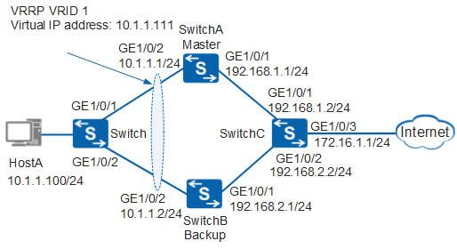
Networking Requirements
The host uses SwitchA as the default gateway to connect to the Internet. When SwitchA becomes faulty, SwitchB functions as the gateway. This implements gateway backup.
After SwitchA recovers, it preempts to be the master to transmit data after a preemption delay of 20s.
In this scenario, to avoid loops, ensure that all connected interfaces have STP disabled and connected interfaces are removed from VLAN 1. If STP is enabled and VLANIF interfaces of switches are used to construct a Layer 3 ring network, an interface on the network will be blocked. As a result, Layer 3 services on the network cannot run normally.
Configuration Roadmap
A VRRP group in active/standby mode is used to implement gateway backup. The configuration roadmap is as follows:
- Assign an IP address to each interface and configure a routing protocol to ensure network connectivity.
- Configure a VRRP group on SwitchA and SwitchB. Set a higher priority for SwitchA so that SwitchA functions as the master to forward traffic, and set the preemption delay to 20s on SwitchA. Set a lower priority for SwitchB so that SwitchB functions as the backup.
Procedure
- Configure devices to ensure network connectivity.
# Assign an IP address to each interface. SwitchA is used as an example. The configurations of SwitchB and SwitchC are similar to the configuration of SwitchA, and are not mentioned here. For details, see the configuration files.
<HUAWEI> system-view
[HUAWEI] sysname SwitchA
[SwitchA] vlan batch 100 300
[SwitchA] interface gigabitethernet 1/0/1
[SwitchA-GigabitEthernet1/0/1] port link-type hybrid
[SwitchA-GigabitEthernet1/0/1] port hybrid pvid vlan 300
[SwitchA-GigabitEthernet1/0/1] port hybrid untagged vlan 300
[SwitchA-GigabitEthernet1/0/1] quit
[SwitchA] interface gigabitethernet 1/0/2
[SwitchA-GigabitEthernet1/0/2] port link-type hybrid
[SwitchA-GigabitEthernet1/0/2] port hybrid pvid vlan 100
[SwitchA-GigabitEthernet1/0/2] port hybrid untagged vlan 100
[SwitchA-GigabitEthernet1/0/2] quit
[SwitchA] interface vlanif 100
[SwitchA-Vlanif100] ip address 10.1.1.1 24
[SwitchA-Vlanif100] quit
[SwitchA] interface vlanif 300
[SwitchA-Vlanif300] ip address 192.168.1.1 24
[SwitchA-Vlanif300] quit
# Configure Layer 2 forwarding on the switch.
<HUAWEI> system-view
[HUAWEI] sysname Switch
[Switch] vlan 100
[Switch-vlan100] quit
[Switch] interface gigabitethernet 1/0/1
[Switch-GigabitEthernet1/0/1] port link-type hybrid
[Switch-GigabitEthernet1/0/1] port hybrid pvid vlan 100
[Switch-GigabitEthernet1/0/1] port hybrid untagged vlan 100
[Switch-GigabitEthernet1/0/1] quit
[Switch] interface gigabitethernet 1/0/2
[Switch-GigabitEthernet1/0/2] port link-type hybrid
[Switch-GigabitEthernet1/0/2] port hybrid pvid vlan 100
[Switch-GigabitEthernet1/0/2] port hybrid untagged vlan 100
[Switch-GigabitEthernet1/0/2] quit
# Configure OSPF on SwitchA, SwitchB, and SwitchC. SwitchA is used as an example. The configurations of SwitchB and SwitchC are similar to the configuration of SwitchA, and are not mentioned here. For details, see the configuration files.
[SwitchA] ospf 1
[SwitchA-ospf-1] area 0
[SwitchA-ospf-1-area-0.0.0.0] network 10.1.1.0 0.0.0.255
[SwitchA-ospf-1-area-0.0.0.0] network 192.168.1.0 0.0.0.255
[SwitchA-ospf-1-area-0.0.0.0] quit
[SwitchA-ospf-1] quit
- Configure a VRRP group.
# Configure VRRP group 1 on SwitchA, and set the priority of SwitchA to 120 and the preemption delay to 20s.
[SwitchA] interface vlanif 100
[SwitchA-Vlanif100] vrrp vrid 1 virtual-ip 10.1.1.111
[SwitchA-Vlanif100] vrrp vrid 1 priority 120                  //The default priority of a device in a VRRP group is 100. Change the priority of the master to be higher than that of the backup.
[SwitchA-Vlanif100] vrrp vrid 1 preempt-mode timer delay 20   //A device in a VRRP group uses immediate preemption by default. Change the preemption delay of the master to prevent service interruptions on an unstable network where devices in the VRRP group preempt to be the master.
[SwitchA-Vlanif100] quit
# Configure VRRP group 1 on SwitchB. SwitchB uses default value 100.
[SwitchB] interface vlanif 100
[SwitchB-Vlanif100] vrrp vrid 1 virtual-ip 10.1.1.111
[SwitchB-Vlanif100] quit
- Verify the configuration.
# After the configuration is complete, run the display vrrp command on SwitchA and SwitchB. You can see that SwitchA is in Master state and SwitchB is in Backup state.
[SwitchA] display vrrp
  Vlanif100 | Virtual Router 1
    State : Master
    Virtual IP : 10.1.1.111
    Master IP : 10.1.1.1
    PriorityRun : 120
    PriorityConfig : 120
    MasterPriority : 120
    Preempt : YES   Delay Time : 20 s
    TimerRun : 1 s
    TimerConfig : 1 s
    Auth type : NONE
    Virtual MAC : 0000-5e00-0101
    Check TTL : YES
    Config type : normal-vrrp
    Backup-forward : disabled
    Create time : 2012-01-12 20:15:46
    Last change time : 2012-01-12 20:15:46
[SwitchB] display vrrp
  Vlanif100 | Virtual Router 1
    State : Backup
    Virtual IP : 10.1.1.111
    Master IP : 10.1.1.1
    PriorityRun : 100
    PriorityConfig : 100
    MasterPriority : 120
    Preempt : YES   Delay Time : 0 s
    TimerRun : 1 s
    TimerConfig : 1 s
    Auth type : NONE
    Virtual MAC : 0000-5e00-0101
    Check TTL : YES
    Config type : normal-vrrp
    Backup-forward : disabled
    Create time : 2012-01-12 20:15:46
    Last change time : 2012-01-12 20:15:46
# Run the display ip routing-table command on SwitchA and SwitchB. The command output shows that a direct route to the virtual IP address exists in the routing table of SwitchA and an OSPF route to the virtual IP address exists in the routing table of SwitchB. The command output on SwitchA and SwitchB is as follows:
[SwitchA] display ip routing-table
Route Flags: R - relay, D - download to fib, T - to vpn-instance
------------------------------------------------------------------------------
Routing Tables: Public
         Destinations : 9       Routes : 10

Destination/Mask    Proto   Pre  Cost      Flags NextHop         Interface

     10.1.1.0/24    Direct   0     0         D      10.1.1.1        Vlanif100
     10.1.1.1/32    Direct   0     0         D      127.0.0.1       Vlanif100
 10.1.1.111/32    Direct  0     0         D      127.0.0.1      Vlanif100
     127.0.0.0/8    Direct   0    0          D      127.0.0.1       InLoopBack0
    127.0.0.1/32    Direct   0    0          D      127.0.0.1       InLoopBack0
   172.16.1.0/24    OSPF     10   2          D      192.168.1.2     Vlanif300
  192.168.1.0/24    Direct   0    0          D      192.168.1.1     Vlanif300
  192.168.1.1/32    Direct   0    0          D      127.0.0.1       Vlanif300
  192.168.2.0/24    OSPF     10   2          D      10.1.1.2        Vlanif100
                    OSPF     10   2          D      192.168.1.2     Vlanif300
[SwitchB] display ip routing-table
Route Flags: R - relay, D - download to fib, T - to vpn-instance
------------------------------------------------------------------------------
Routing Tables: Public
         Destinations : 9       Routes : 10

Destination/Mask    Proto   Pre  Cost      Flags NextHop         Interface

     10.1.1.0/24    Direct   0     0         D     10.1.1.2        Vlanif100
     10.1.1.2/32    Direct   0     0         D     127.0.0.1       Vlanif100
 10.1.1.111/32    OSPF    10    2         D     10.1.1.1       Vlanif100
     127.0.0.0/8    Direct   0     0         D     127.0.0.1       InLoopBack0
    127.0.0.1/32    Direct   0     0         D     127.0.0.1       InLoopBack0
   172.16.1.0/24    OSPF     10    2         D     192.168.2.2     Vlanif200
  192.168.1.0/24    OSPF     10    2         D     10.1.1.1        Vlanif100
                    OSPF     10    2         D     192.168.2.2     Vlanif200
  192.168.2.0/24    Direct   0     0         D     192.168.2.1     Vlanif200
  192.168.2.1/32    Direct   0     0         D     127.0.0.1       Vlanif200
# Run the shutdown command on GE1/0/2 of SwitchA to simulate a link fault.
[SwitchA] interface gigabitethernet 1/0/2
[SwitchA-GigabitEthernet1/0/2] shutdown
[SwitchA-GigabitEthernet1/0/2] quit
# Run the display vrrp command on SwitchB to view the VRRP status. The command output shows that SwitchB is in Master state.
[SwitchB] display vrrp
  Vlanif100 | Virtual Router 1
    State : Master
    Virtual IP : 10.1.1.111
    Master IP : 10.1.1.2
    PriorityRun : 100
    PriorityConfig : 100
    MasterPriority : 100
    Preempt : YES   Delay Time : 0 s
    TimerRun : 1 s
    TimerConfig : 1 s
    Auth type : NONE
    Virtual MAC : 0000-5e00-0101
    Check TTL : YES
    Config type : normal-vrrp
    Backup-forward : disabled
    Create time : 2012-01-12 20:15:46
    Last change time : 2012-01-12 20:18:40
# Run the undo shutdown command on GE1/0/2 of SwitchA.
[SwitchA] interface gigabitethernet 1/0/2
[SwitchA-GigabitEthernet1/0/2] undo shutdown
[SwitchA-GigabitEthernet1/0/2] quit
# After 20s, run the display vrrp command on SwitchA to view the VRRP status. The command output shows that SwitchA is in Master state.
[SwitchA] display vrrp
  Vlanif100 | Virtual Router 1
    State : Master
    Virtual IP : 10.1.1.111
    Master IP : 10.1.1.1
    PriorityRun : 120
    PriorityConfig : 120
    MasterPriority : 120
    Preempt : YES   Delay Time : 20 s
    TimerRun : 1 s
    TimerConfig : 1 s
    Auth type : NONE
    Virtual MAC : 0000-5e00-0101
    Check TTL : YES
    Config type : normal-vrrp
    Backup-forward : disabled
    Create time : 2012-01-12 20:15:46
    Last change time : 2012-01-12 20:20:56
Configuration Files
Configuration file of SwitchA
#
sysname SwitchA
#
vlan batch 100 300
#
interface Vlanif100
 ip address 10.1.1.1 255.255.255.0
 vrrp vrid 1 virtual-ip 10.1.1.111
 vrrp vrid 1 priority 120
 vrrp vrid 1 preempt-mode timer delay 20
#
interface Vlanif300
 ip address 192.168.1.1 255.255.255.0
#
interface GigabitEthernet1/0/1
 port link-type hybrid
 port hybrid pvid vlan 300
 port hybrid untagged vlan 300
#
interface GigabitEthernet1/0/2
 port link-type hybrid
 port hybrid pvid vlan 100
 port hybrid untagged vlan 100
#
ospf 1
 area 0.0.0.0
  network 10.1.1.0 0.0.0.255
  network 192.168.1.0 0.0.0.255
#
return
Configuration file of SwitchB
#
sysname SwitchB
#
vlan batch 100 200
#
interface Vlanif100
 ip address 10.1.1.2 255.255.255.0
 vrrp vrid 1 virtual-ip 10.1.1.111
#
interface Vlanif200
 ip address 192.168.2.1 255.255.255.0
#
interface GigabitEthernet1/0/1
 port link-type hybrid
 port hybrid pvid vlan 200
 port hybrid untagged vlan 200
#
interface GigabitEthernet1/0/2
 port link-type hybrid
 port hybrid pvid vlan 100
 port hybrid untagged vlan 100
#
ospf 1
 area 0.0.0.0
  network 10.1.1.0 0.0.0.255
  network 192.168.2.0 0.0.0.255
#
return
Configuration file of SwitchC
#
sysname SwitchC
#
vlan batch 200 300 400
#
interface Vlanif200
 ip address 192.168.2.2 255.255.255.0
#
interface Vlanif300
 ip address 192.168.1.2 255.255.255.0
#
interface Vlanif400
 ip address 172.16.1.1 255.255.255.0
#
interface GigabitEthernet1/0/1
 port link-type hybrid
 port hybrid pvid vlan 300
 port hybrid untagged vlan 300
#
interface GigabitEthernet1/0/2
 port link-type hybrid
 port hybrid pvid vlan 200
 port hybrid untagged vlan 200
#
interface GigabitEthernet1/0/3
 port link-type hybrid
 port hybrid pvid vlan 400
 port hybrid untagged vlan 400
#
ospf 1
 area 0.0.0.0
  network 172.16.1.0 0.0.0.255
  network 192.168.1.0 0.0.0.255
  network 192.168.2.0 0.0.0.255
#
return
Configuration file of the switch
#
sysname Switch
#
vlan batch 100
#
interface GigabitEthernet1/0/1
 port link-type hybrid
 port hybrid pvid vlan 100
 port hybrid untagged vlan 100
#
interface GigabitEthernet1/0/2
 port link-type hybrid
 port hybrid pvid vlan 100
 port hybrid untagged vlan 100
#
return
Video
Applicable Product Models and Versions
Product |
Product Model |
Software Version |
|---|---|---|
S2700 |
S2720-EI |
V200R011C10, V200R012C00, V200R013C00, V200R019C00, V200R019C10 |
S3700 |
S3700-EI |
V100R006C05 |
S3700-HI |
V200R001C00 |
|
S5700 |
S5720-LI, S5720S-LI |
V200R010C00, V200R011C00, V200R011C10, V200R012(C00&C20), V200R013C00, V200R019C00, V200R019C10 |
S5720-SI, S5720S-SI |
V200R008C00, V200R009C00, V200R010C00, V200R011C00, V200R011C10, V200R012C00, V200R013C00, V200R019C00, V200R019C10 |
|
S5720I-SI |
V200R012C00, V200R013C00, V200R019C00, V200R019C10 |
|
S5700-EI |
V200R001(C00&C01), V200R002C00, V200R003C00, V200R005(C00&C01&C02&C03) |
|
S5700-HI |
V200R001(C00&C01), V200R002C00, V200R003C00, V200R005(C00SPC500&C01&C02) |
|
S5710-EI |
V200R001C00, V200R002C00, V200R003C00, V200R005(C00&C02) |
|
S5720-EI |
V200R007C00, V200R008C00, V200R009C00, V200R010C00, V200R011C00, V200R011C10, V200R012C00, V200R013C00, V200R019C00, V200R019C10 |
|
S5710-HI |
V200R003C00, V200R005(C00&C02&C03) |
|
S5720-HI |
V200R006C00, V200R007(C00&C10), V200R008C00, V200R009C00, V200R010C00, V200R011C00, V200R011C10, V200R012C00, V200R013C00, V200R019C00, V200R019C10 |
|
S5730-HI |
V200R012C00, V200R013C00, V200R019C00, V200R019C10 |
|
S5730-SI |
V200R011C10, V200R012C00, V200R013C00, V200R019C00, V200R019C10 |
|
S5730S-EI |
V200R011C10, V200R012C00, V200R013C00, V200R019C00, V200R019C10 |
|
S5731-H |
V200R013C02, V200R019C00, V200R019C10 |
|
S5731-S, S5731S-S |
V200R019C00, V200R019C10 |
|
S5731S-H |
V200R019C00, V200R019C10 |
|
S5732-H |
V200R019C00, V200R019C10 |
|
S5735-L, S5735S-L |
V200R019C00, V200R019C10 |
|
S5735S-L-M |
V200R019C00, V200R019C10 |
|
S5735-S, S5735S-S |
V200R019C00, V200R019C10 |
|
S5700 |
S5735-S-I |
V200R019C10 |
S6700 |
S6720-LI, S6720S-LI |
V200R011C00, V200R011C10, V200R012C00, V200R013C00, V200R019C00, V200R019C10 |
S6720-SI, S6720S-SI |
V200R011C00, V200R011C10, V200R012C00, V200R013C00, V200R019C00, V200R019C10 |
|
S6700-EI |
V200R001(C00&C01), V200R002C00, V200R003C00, V200R005(C00&C01&C02) |
|
S6720-EI |
V200R008C00, V200R009C00, V200R010C00, V200R011C00, V200R011C10, V200R012C00, V200R013C00, V200R019C00, V200R019C10 |
|
S6720S-EI |
V200R009C00, V200R010C00, V200R011C00, V200R011C10, V200R012C00, V200R013C00, V200R019C00, V200R019C10 |
|
S6720-HI |
V200R012C00, V200R013C00, V200R019C00, V200R019C10 |
|
S6730-H |
V200R013C02, V200R019C00, V200R019C10 |
|
S6730S-H |
V200R019C10 |
|
S6730-S, S6730S-S |
V200R019C00, V200R019C10 |
|
S7700 |
S7703, S7706, S7712 |
V200R001(C00&C01), V200R002C00, V200R003C00, V200R005C00, V200R006C00, V200R007C00, V200R008C00, V200R009C00, V200R010C00, V200R011C10, V200R012C00, V200R013C00, V200R013C02, V200R019C00, V200R019C10 |
S7703 PoE |
V200R013C00, V200R019C00, V200R019C10 |
|
S7706 PoE |
V200R013C00, V200R019C00, V200R019C10 |
|
S9700 |
S9703, S9706, S9712 |
V200R001(C00&C01), V200R002C00, V200R003C00, V200R005C00, V200R006C00, V200R007(C00&C10), V200R008C00, V200R009C00, V200R010C00, V200R011C10, V200R012C00, V200R013C00 |