Example for Configuring a VRRP Group in Load Balancing Mode
VRRP Load Balancing Overview
In load balancing mode, multiple devices transmit service traffic simultaneously. Therefore, the load balancing mode requires two or more virtual routers. Each virtual router contains one master and multiple backups, and the master in each virtual router can be different.
- Multiple VRRP groups need to be created, and the master in each VRRP group can be different.
- A VRRP device can join multiple VRRP groups and has different priorities in different VRRP groups.
Configuration Notes
In V200R003 and earlier versions, VRRP can be configured only on the VLANIF interface.
In V200R005 and later versions, VRRP can be configured on the VLANIF interface and Layer 3 Ethernet interface.
For a modular switch in V200R006 and later versions, VRRP can be configured on the VLANIF interface, Layer 3 Ethernet interface, Dot1q termination sub-interface, and QinQ termination sub-interface.
For a fixed switch in V200R009 and later versions, VRRP can be configured on the VLANIF interface, Layer 3 Ethernet interface, and sub-interface.
- Ensure that each device of the same VRRP group is configured with the same VRID.
VRRP groups must use different virtual IP addresses. The virtual IP address of a VRRP group must be on the same network segment as the IP address of the interface where the VRRP group is configured.
For applicable product models and versions, see Applicable Product Models and Versions.

For details about software mappings, visit Hardware Query Tool and search for the desired product model.
Networking Requirements
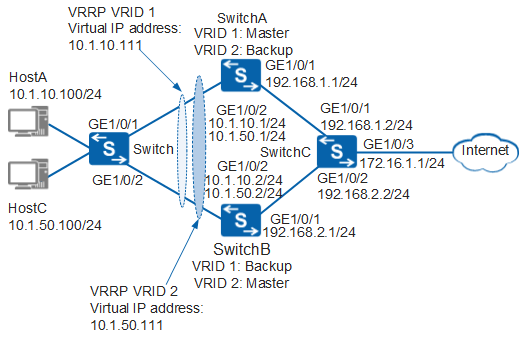
In Figure 1, HostA and HostC are dual-homed to SwitchA and SwitchB through the switch. To reduce the load of data traffic on SwitchA, HostA uses SwitchA as the default gateway to connect to the Internet, and SwitchB functions as the backup gateway. HostC uses SwitchB as the default gateway to connect to the Internet, and SwitchA functions as the backup gateway. This implements load balancing.
In this scenario, to avoid loops, ensure that all connected interfaces have STP disabled and connected interfaces are removed from VLAN 1. If STP is enabled and VLANIF interfaces of switches are used to construct a Layer 3 ring network, an interface on the network will be blocked. As a result, Layer 3 services on the network cannot run normally.
Configuration Roadmap
A VRRP group in load balancing mode is used to implement load balancing. The configuration roadmap is as follows:
- Assign an IP address to each interface and configure a routing protocol to ensure network connectivity.
- Create VRRP groups 1 and 2 on SwitchA and SwitchB. In VRRP group 1, configure SwitchA as the master and SwitchB as the backup. In VRRP group 2, configure SwitchB as the master and SwitchA as the backup.
Procedure
- Configure devices to ensure network connectivity.
# Assign an IP address to each interface. SwitchA is used as an example. The configurations of SwitchB and SwitchC are similar to the configuration of SwitchA, and are not mentioned here. For details, see the configuration files.
<HUAWEI> system-view
[HUAWEI] sysname SwitchA
[SwitchA] vlan batch 100 300 500
[SwitchA] interface gigabitethernet 1/0/1
[SwitchA-GigabitEthernet1/0/1] port link-type trunk
[SwitchA-GigabitEthernet1/0/1] port trunk allow-pass vlan 300
[SwitchA-GigabitEthernet1/0/1] quit
[SwitchA] interface gigabitethernet 1/0/2
[SwitchA-GigabitEthernet1/0/2] port link-type trunk
[SwitchA-GigabitEthernet1/0/2] port trunk allow-pass vlan 100 500
[SwitchA-GigabitEthernet1/0/2] quit
[SwitchA] interface vlanif 100
[SwitchA-Vlanif100] ip address 10.1.10.1 24
[SwitchA-Vlanif100] quit
[SwitchA] interface vlanif 500
[SwitchA-Vlanif500] ip address 10.1.50.1 24
[SwitchA-Vlanif500] quit
[SwitchA] interface vlanif 300
[SwitchA-Vlanif300] ip address 192.168.1.1 24
[SwitchA-Vlanif300] quit
# Configure Layer 2 forwarding on the switch.
<HUAWEI> system-view
[HUAWEI] sysname Switch
[Switch] vlan batch 100 500
[Switch] interface gigabitethernet 1/0/1
[Switch-GigabitEthernet1/0/1] port link-type trunk
[Switch-GigabitEthernet1/0/1] port trunk allow-pass vlan 100 500
[Switch-GigabitEthernet1/0/1] quit
[Switch] interface gigabitethernet 1/0/2
[Switch-GigabitEthernet1/0/2] port link-type trunk
[Switch-GigabitEthernet1/0/2] port trunk allow-pass vlan 100 500
[Switch-GigabitEthernet1/0/2] quit
# Configure OSPF on SwitchA, SwitchB, and SwitchC. SwitchA is used as an example. The configurations of SwitchB and SwitchC are similar to the configuration of SwitchA, and are not mentioned here. For details, see the configuration files.
[SwitchA] ospf 1
[SwitchA-ospf-1] area 0
[SwitchA-ospf-1-area-0.0.0.0] network 10.1.10.0 0.0.0.255
[SwitchA-ospf-1-area-0.0.0.0] network 10.1.50.0 0.0.0.255
[SwitchA-ospf-1-area-0.0.0.0] network 192.168.1.0 0.0.0.255
[SwitchA-ospf-1-area-0.0.0.0] quit
[SwitchA-ospf-1] quit
- Configure a VRRP group.
# Configure VRRP group 1 on SwitchA and SwitchB, set the priority of SwitchA to 120 and the preemption delay to 20s, and set the default priority for SwitchB.
[SwitchA] interface vlanif 100
[SwitchA-Vlanif100] vrrp vrid 1 virtual-ip 10.1.10.111
[SwitchA-Vlanif100] vrrp vrid 1 priority 120                 //The default priority of a device in a VRRP group is 100. Change the priority of the master to be higher than that of the backup.
[SwitchA-Vlanif100] vrrp vrid 1 preempt-mode timer delay 20  //A device in a VRRP group uses immediate preemption by default. Change the preemption delay of the master to prevent service interruptions on an unstable network where devices in the VRRP group preempt to be the master.
[SwitchA-Vlanif100] quit
[SwitchB] interface vlanif 100
[SwitchB-Vlanif100] vrrp vrid 1 virtual-ip 10.1.10.111
[SwitchB-Vlanif100] quit
# Configure VRRP group 2 on SwitchA and SwitchB, set the priority of SwitchB to 120 and the preemption delay to 20s, and set the default priority for SwitchA.
[SwitchB] interface vlanif 500
[SwitchB-Vlanif500] vrrp vrid 2 virtual-ip 10.1.50.111
[SwitchB-Vlanif500] vrrp vrid 2 priority 120                 //The default priority of a device in a VRRP group is 100. Change the priority of the master to be higher than that of the backup.
[SwitchB-Vlanif500] vrrp vrid 2 preempt-mode timer delay 20  //A device in a VRRP group uses immediate preemption by default. Change the preemption delay of the master to prevent service interruptions on an unstable network where devices in the VRRP group preempt to be the master.
[SwitchB-Vlanif500] quit
[SwitchA] interface vlanif 500
[SwitchA-Vlanif500] vrrp vrid 2 virtual-ip 10.1.50.111
[SwitchA-Vlanif500] quit
- Verify the configuration.
# After the configuration is complete, run the display vrrp command on SwitchA. You can see that SwitchA is the master in VRRP group 1 and the backup in VRRP group 2.
[SwitchA] display vrrp
  Vlanif100 | Virtual Router 1
    State : Master
    Virtual IP : 10.1.10.111
    Master IP : 10.1.10.1
    PriorityRun : 120
    PriorityConfig : 120
    MasterPriority : 120
    Preempt : YES   Delay Time : 20 s
    TimerRun : 1 s
    TimerConfig : 1 s
    Auth type : NONE
    Virtual MAC : 0000-5e00-0101
    Check TTL : YES
    Config type : normal-vrrp
    Backup-forward : disabled
    Create time : 2012-01-12 20:15:46
    Last change time : 2012-01-12 20:15:46

  Vlanif500 | Virtual Router 2
    State : Backup
    Virtual IP : 10.1.50.111
    Master IP : 10.1.50.2
    PriorityRun : 100
    PriorityConfig : 100
    MasterPriority : 120
    Preempt : YES   Delay Time : 0 s
    TimerRun : 1 s
    TimerConfig : 1 s
    Auth type : NONE
    Virtual MAC : 0000-5e00-0102
    Check TTL : YES
    Config type : normal-vrrp
    Backup-forward : disabled
    Create time : 2012-01-12 20:15:46
    Last change time : 2012-01-12 20:15:46
# After the configuration is complete, run the display vrrp command on SwitchB. You can see that SwitchB is the backup in VRRP group 1 and the master in VRRP group 2.
[SwitchB] display vrrp
  Vlanif100 | Virtual Router 1
    State : Backup
    Virtual IP : 10.1.10.111
    Master IP : 10.1.10.1
    PriorityRun : 100
    PriorityConfig : 100
    MasterPriority : 120
    Preempt : YES   Delay Time : 0 s
    TimerRun : 1 s
    TimerConfig : 1 s
    Auth type : NONE
    Virtual MAC : 0000-5e00-0101
    Check TTL : YES
    Config type : normal-vrrp
    Backup-forward : disabled
    Create time : 2012-01-12 20:15:46
    Last change time : 2012-01-12 20:15:46

  Vlanif500 | Virtual Router 2
    State : Master
    Virtual IP : 10.1.50.111
    Master IP : 10.1.50.2
    PriorityRun : 120
    PriorityConfig : 120
    MasterPriority : 120
    Preempt : YES   Delay Time : 20 s
    TimerRun : 1 s
    TimerConfig : 1 s
    Auth type : NONE
    Virtual MAC : 0000-5e00-0102
    Check TTL : YES
    Config type : normal-vrrp
    Backup-forward : disabled
    Create time : 2012-01-12 20:15:46
    Last change time : 2012-01-12 20:15:46
Configuration Files
Configuration file of SwitchA
#
sysname SwitchA
#
vlan batch 100 300 500
#
interface Vlanif100
 ip address 10.1.10.1 255.255.255.0
 vrrp vrid 1 virtual-ip 10.1.10.111
 vrrp vrid 1 priority 120
 vrrp vrid 1 preempt-mode timer delay 20
#
interface Vlanif300
 ip address 192.168.1.1 255.255.255.0
#
interface Vlanif500
 ip address 10.1.50.1 255.255.255.0
 vrrp vrid 2 virtual-ip 10.1.50.111
#
interface GigabitEthernet1/0/1
 port link-type trunk
 port trunk allow-pass vlan 300
#
interface GigabitEthernet1/0/2
 port link-type trunk
 port trunk allow-pass vlan 100 500
#
ospf 1
 area 0.0.0.0
  network 10.1.10.0 0.0.0.255
  network 10.1.50.0 0.0.0.255
  network 192.168.1.0 0.0.0.255
#
return
Configuration file of SwitchB
#
sysname SwitchB
#
vlan batch 100 200 500
#
interface Vlanif100
 ip address 10.1.10.2 255.255.255.0
 vrrp vrid 1 virtual-ip 10.1.10.111
#
interface Vlanif200
 ip address 192.168.2.1 255.255.255.0
#
interface Vlanif500
 ip address 10.1.50.2 255.255.255.0
 vrrp vrid 2 virtual-ip 10.1.50.111
 vrrp vrid 2 priority 120
 vrrp vrid 2 preempt-mode timer delay 20
#
interface GigabitEthernet1/0/1
 port link-type trunk
 port trunk allow-pass vlan 200
#
interface GigabitEthernet1/0/2
 port link-type trunk
 port trunk allow-pass vlan 100 500
#
ospf 1
 area 0.0.0.0
  network 10.1.10.0 0.0.0.255
  network 10.1.50.0 0.0.0.255
  network 192.168.2.0 0.0.0.255
#
return
Configuration file of SwitchC
#
sysname SwitchC
#
vlan batch 200 300 400
#
interface Vlanif200
 ip address 192.168.2.2 255.255.255.0
#
interface Vlanif300
 ip address 192.168.1.2 255.255.255.0
#
interface Vlanif400
 ip address 172.16.1.1 255.255.255.0
#
interface GigabitEthernet1/0/1
 port link-type trunk
 port trunk allow-pass vlan 300
#
interface GigabitEthernet1/0/2
 port link-type trunk
 port trunk allow-pass vlan 200
#
interface GigabitEthernet1/0/3
 port link-type trunk
 port trunk allow-pass vlan 400
#
ospf 1
 area 0.0.0.0
  network 172.16.1.0 0.0.0.255
  network 192.168.1.0 0.0.0.255
  network 192.168.2.0 0.0.0.255
#
return
Configuration file of the switch
#
sysname Switch
#
vlan batch 100 500
#
interface GigabitEthernet1/0/1
 port link-type trunk
 port trunk allow-pass vlan 100 500
#
interface GigabitEthernet1/0/2
 port link-type trunk
 port trunk allow-pass vlan 100 500
#
return
Applicable Product Models and Versions
Product |
Product Model |
Software Version |
|---|---|---|
S2700 |
S2720-EI |
V200R011C10, V200R012C00, V200R013C00, V200R019C00, V200R019C10 |
S3700 |
S3700-EI |
V100R006C05 |
S3700-HI |
V200R001C00 |
|
S5700 |
S5720-LI, S5720S-LI |
V200R010C00, V200R011C00, V200R011C10, V200R012(C00&C20), V200R013C00, V200R019C00, V200R019C10 |
S5720-SI, S5720S-SI |
V200R008C00, V200R009C00, V200R010C00, V200R011C00, V200R011C10, V200R012C00, V200R013C00, V200R019C00, V200R019C10 |
|
S5720I-SI |
V200R012C00, V200R013C00, V200R019C00, V200R019C10 |
|
S5700-EI |
V200R001(C00&C01), V200R002C00, V200R003C00, V200R005(C00&C01&C02&C03) |
|
S5700-HI |
V200R001(C00&C01), V200R002C00, V200R003C00, V200R005(C00SPC500&C01&C02) |
|
S5710-EI |
V200R001C00, V200R002C00, V200R003C00, V200R005(C00&C02) |
|
S5720-EI |
V200R007C00, V200R008C00, V200R009C00, V200R010C00, V200R011C00, V200R011C10, V200R012C00, V200R013C00, V200R019C00, V200R019C10 |
|
S5710-HI |
V200R003C00, V200R005(C00&C02&C03) |
|
S5720-HI |
V200R006C00, V200R007(C00&C10), V200R008C00, V200R009C00, V200R010C00, V200R011C00, V200R011C10, V200R012C00, V200R013C00, V200R019C00, V200R019C10 |
|
S5730-HI |
V200R012C00, V200R013C00, V200R019C00, V200R019C10 |
|
S5730-SI |
V200R011C10, V200R012C00, V200R013C00, V200R019C00, V200R019C10 |
|
S5730S-EI |
V200R011C10, V200R012C00, V200R013C00, V200R019C00, V200R019C10 |
|
S5731-H |
V200R013C02, V200R019C00, V200R019C10 |
|
S5731-S, S5731S-S |
V200R019C00, V200R019C10 |
|
S5731S-H |
V200R019C00, V200R019C10 |
|
S5732-H |
V200R019C00, V200R019C10 |
|
S5735-L, S5735S-L |
V200R019C00, V200R019C10 |
|
S5735S-L-M |
V200R019C00, V200R019C10 |
|
S5735-S, S5735S-S |
V200R019C00, V200R019C10 |
|
S5700 |
S5735-S-I |
V200R019C10 |
S6700 |
S6720-LI, S6720S-LI |
V200R011C00, V200R011C10, V200R012C00, V200R013C00, V200R019C00, V200R019C10 |
S6720-SI, S6720S-SI |
V200R011C00, V200R011C10, V200R012C00, V200R013C00, V200R019C00, V200R019C10 |
|
S6700-EI |
V200R001(C00&C01), V200R002C00, V200R003C00, V200R005(C00&C01&C02) |
|
S6720-EI |
V200R008C00, V200R009C00, V200R010C00, V200R011C00, V200R011C10, V200R012C00, V200R013C00, V200R019C00, V200R019C10 |
|
S6720S-EI |
V200R009C00, V200R010C00, V200R011C00, V200R011C10, V200R012C00, V200R013C00, V200R019C00, V200R019C10 |
|
S6720-HI |
V200R012C00, V200R013C00, V200R019C00, V200R019C10 |
|
S6730-H |
V200R013C02, V200R019C00, V200R019C10 |
|
S6730S-H |
V200R019C10 |
|
S6730-S, S6730S-S |
V200R019C00, V200R019C10 |
|
S7700 |
S7703, S7706, S7712 |
V200R001(C00&C01), V200R002C00, V200R003C00, V200R005C00, V200R006C00, V200R007C00, V200R008C00, V200R009C00, V200R010C00, V200R011C10, V200R012C00, V200R013C00, V200R013C02, V200R019C00, V200R019C10 |
S7703 PoE |
V200R013C00, V200R019C00, V200R019C10 |
|
S7706 PoE |
V200R013C00, V200R019C00, V200R019C10 |
|
S9700 |
S9703, S9706, S9712 |
V200R001(C00&C01), V200R002C00, V200R003C00, V200R005C00, V200R006C00, V200R007(C00&C10), V200R008C00, V200R009C00, V200R010C00, V200R011C10, V200R012C00, V200R013C00 |