Example for Configuring Association Between VRRP and BFD to Implement a Rapid Active/Standby Switchover
Overview of Association Between VRRP and BFD
A VRRP group sends and receives VRRP Advertisement packets to determine the master and backup states, thereby implementing redundancy. If links connected to a VRRP group fail, VRRP Advertisement packets cannot be sent for negotiation. A backup will switch to the master after a period of time three times that of the interval during which VRRP Advertisement packets are sent. During the switchover period, service traffic is still sent to the original master, causing user traffic loss.
BFD can rapidly detect connectivity of links and routes on the network. Association between VRRP and BFD implements a fast active/standby switchover within 1 second. A BFD session is set up between the master and backup and is bound to a VRRP group. BFD detects faults of the VRRP group. When a fault occurs, BFD notifies the VRRP group that an active/standby switchover is being performed, greatly reducing the service interruption time.
Configuration Notes
In V200R003 and earlier versions, VRRP can be configured only on the VLANIF interface.
In V200R005 and later versions, VRRP can be configured on the VLANIF interface and Layer 3 Ethernet interface.
For a modular switch in V200R006 and later versions, VRRP can be configured on the VLANIF interface, Layer 3 Ethernet interface, Dot1q termination sub-interface, and QinQ termination sub-interface.
For a fixed switch in V200R009 and later versions, VRRP can be configured on the VLANIF interface, Layer 3 Ethernet interface, and sub-interface.
- Ensure that each device of the same VRRP group is configured with the same VRID.
VRRP groups must use different virtual IP addresses. The virtual IP address of a VRRP group must be on the same network segment as the IP address of the interface where the VRRP group is configured.
Multiple VRRP groups can monitor a BFD session, and a VRRP group can monitor a maximum of eight BFD sessions simultaneously.
For applicable product models and versions, see Applicable Product Models and Versions.

For details about software mappings, visit Hardware Query Tool and search for the desired product model.
Networking Requirements
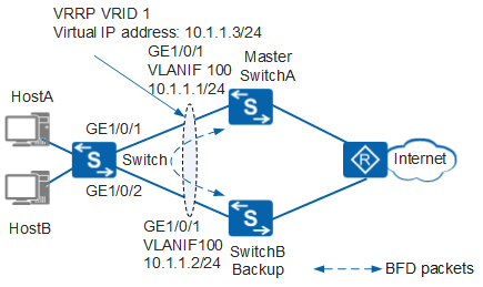
In Figure 1, hosts on a LAN are dual-homed to SwitchA and SwitchB through the switch. A VRRP group is established on SwitchA and SwitchB, and SwitchA is the master.
When SwitchA or a link between SwitchA and SwitchB is faulty, VRRP packets are sent after VRRP negotiation is complete. To speed up link switchovers, deploy a BFD session on the link and associate the VRRP group with the BFD session. When the interface on the master or the link fails, the BFD session rapidly detects the fault and notifies the VRRP group of the fault. After receiving the notification, the VRRP group performs a rapid active/standby switchover. The backup becomes the Master and takes over traffic. This reduces the impact of the fault on service transmission.
In this scenario, to avoid loops, ensure that all connected interfaces have STP disabled and connected interfaces are removed from VLAN 1. If STP is enabled and VLANIF interfaces of switches are used to construct a Layer 3 ring network, an interface on the network will be blocked. As a result, Layer 3 services on the network cannot run normally.
Configuration Roadmap
Association between VRRP and BFD is used to implement a rapid active/standby switchover. The configuration roadmap is as follows:
- Assign an IP address to each interface and configure a routing protocol to ensure network connectivity.
- Configure a VRRP group on SwitchA and SwitchB. SwitchA functions as the master, its priority is 120, and the preemption delay is 20s. SwitchB functions as the backup and uses the default priority.
- Configure a static BFD session on SwitchA and SwitchB to monitor the link of the VRRP group.
- Configuration association between BFD and VRRP on SwitchB. When the link is faulty, an active/standby switchover can be performed rapidly.
Procedure
- Configure devices to ensure network connectivity.
# Assign an IP address to each interface. SwitchA is used as an example. The configuration of SwitchB is similar to that of SwitchA.
<HUAWEI> system-view
[HUAWEI] sysname SwitchA
[SwitchA] vlan 100
[SwitchA-vlan100] quit
[SwitchA] interface gigabitethernet 1/0/1
[SwitchA-GigabitEthernet1/0/1] port link-type hybrid
[SwitchA-GigabitEthernet1/0/1] port hybrid pvid vlan 100
[SwitchA-GigabitEthernet1/0/1] port hybrid untagged vlan 100
[SwitchA-GigabitEthernet1/0/1] quit
[SwitchA] interface vlanif 100
[SwitchA-Vlanif100] ip address 10.1.1.1 24
[SwitchA-Vlanif100] quit
# Configure Layer 2 forwarding on the switch.
<HUAWEI> system-view
[HUAWEI] sysname Switch
[Switch] vlan 100
[Switch-vlan100] quit
[Switch] interface gigabitethernet 1/0/1
[Switch-GigabitEthernet1/0/1] port link-type hybrid
[Switch-GigabitEthernet1/0/1] port hybrid pvid vlan 100
[Switch-GigabitEthernet1/0/1] port hybrid untagged vlan 100
[Switch-GigabitEthernet1/0/1] quit
[Switch] interface gigabitethernet 1/0/2
[Switch-GigabitEthernet1/0/2] port link-type hybrid
[Switch-GigabitEthernet1/0/2] port hybrid pvid vlan 100
[Switch-GigabitEthernet1/0/2] port hybrid untagged vlan 100
[Switch-GigabitEthernet1/0/2] quit
# Configure OSPF between SwitchA and SwitchB. SwitchA is used as an example. The configuration of SwitchB is similar to that of SwitchA.
[SwitchA] ospf 1
[SwitchA-ospf-1] area 0
[SwitchA-ospf-1-area-0.0.0.0] network 10.1.1.0 0.0.0.255
[SwitchA-ospf-1-area-0.0.0.0] quit
[SwitchA-ospf-1] quit
- Configure a VRRP group.
# Configure VRRP group 1 on SwitchA, and set the priority of SwitchA to 120 and the preemption delay to 20s.
[SwitchA] interface vlanif 100
[SwitchA-Vlanif100] vrrp vrid 1 virtual-ip 10.1.1.3
[SwitchA-Vlanif100] vrrp vrid 1 priority 120                 //The default priority of a device in a VRRP group is 100. Change the priority of the master to be higher than that of the backup.
[SwitchA-Vlanif100] vrrp vrid 1 preempt-mode timer delay 20  //A device in a VRRP group uses immediate preemption by default. Change the preemption delay of the master to prevent service interruptions on an unstable network where devices in the VRRP group preempt to be the master.
[SwitchA-Vlanif100] quit
# Configure VRRP group 1 on SwitchB. SwitchB uses default value 100.
[SwitchB] interface vlanif 100
[SwitchB-Vlanif100] vrrp vrid 1 virtual-ip 10.1.1.3
[SwitchB-Vlanif100] quit
- Configure a static BFD session.
# Create a BFD session on SwitchA.
[SwitchA] bfd
[SwitchA-bfd] quit
[SwitchA] bfd atob bind peer-ip 10.1.1.2 interface vlanif 100 //Configure a static BFD session to monitor the link of the VRRP group.
[SwitchA-bfd-session-atob] discriminator local 1 //Configure the local discriminator of the BFD session. The local discriminator on SwitchA must be the same as the remote discriminator on SwitchB.
[SwitchA-bfd-session-atob] discriminator remote 2 //Configure the remote discriminator of the BFD session. The remote discriminator on SwitchA must be the same as the local discriminator on SwitchB.
[SwitchA-bfd-session-atob] min-rx-interval 100 //Configure the minimum interval for receiving BFD packets.
[SwitchA-bfd-session-atob] min-tx-interval 100 //Configure the minimum interval for sending BFD packets.
[SwitchA-bfd-session-atob] commit //Commit the BFD session to make the configuration take effect.
[SwitchA-bfd-session-atob] quit
# Create a BFD session on SwitchB.
[SwitchB] bfd
[SwitchB-bfd] quit
[SwitchB] bfd btoa bind peer-ip 10.1.1.1 interface vlanif 100
[SwitchB-bfd-session-btoa] discriminator local 2
[SwitchB-bfd-session-btoa] discriminator remote 1
[SwitchB-bfd-session-btoa] min-rx-interval 100
[SwitchB-bfd-session-btoa] min-tx-interval 100
[SwitchB-bfd-session-btoa] commit
[SwitchB-bfd-session-btoa] quit
Run the display bfd session command on SwitchA and SwitchB. You can see that the BFD session is Up. The display on SwitchA is used as an example.
[SwitchA] display bfd session all
--------------------------------------------------------------------------------
Local Remote PeerIpAddr      State     Type        InterfaceName
--------------------------------------------------------------------------------
1     2      10.1.1.2      Up        S_IP_IF     Vlanif100
--------------------------------------------------------------------------------
     Total UP/DOWN Session Number : 1/0
- Configuration association between BFD and VRRP.
# Configure association between VRRP and BFD on SwitchB. When the BFD session becomes Down, the priority of SwitchB increases by 40.
[SwitchB] interface vlanif 100
[SwitchB-Vlanif100] vrrp vrid 1 track bfd-session 2 increased 40 //The value 2 indicates the local discriminator.
[SwitchB-Vlanif100] quit
- Verify the configuration.
# After the configuration is complete, run the display vrrp command on SwitchA and SwitchB. SwitchA is the master, SwitchB is the backup, and the associated BFD session is in Up state.
[SwitchA] display vrrp
  Vlanif100 | Virtual Router 1
    State : Master
    Virtual IP : 10.1.1.3
    Master IP : 10.1.1.1
    PriorityRun : 120
    PriorityConfig : 120
    MasterPriority : 120
    Preempt : YES   Delay Time : 20 s
    TimerRun : 1 s
    TimerConfig : 1 s
    Auth type : NONE
    Virtual MAC : 0000-5e00-0101
    Check TTL : YES
    Config type : normal-vrrp
    Backup-forward : disabled
    Create time : 2012-01-12 20:15:46
    Last change time : 2012-01-12 20:15:46
[SwitchB] display vrrp
  Vlanif100 | Virtual Router 1
    State : Backup
    Virtual IP : 10.1.1.3
    Master IP : 10.1.1.1
    PriorityRun : 100
    PriorityConfig : 100
    MasterPriority : 120
    Preempt : YES   Delay Time : 0 s
    TimerRun : 1 s
    TimerConfig : 1 s
    Auth type : NONE
    Virtual MAC : 0000-5e00-0101
    Check TTL : YES
    Config type : normal-vrrp
    Backup-forward : disabled
    Track BFD : 2  Priority increased : 40
    BFD-session state : UP
    Create time : 2012-01-12 20:15:46
   Last change time : 2012-01-12 20:15:46
# Run the shutdown command on GE1/0/1 of SwitchA to simulate a link fault. Then run the display vrrp command on SwitchA and SwitchB. You can see that SwitchA is in Initialize state, SwitchB becomes the master, and the associated BFD session becomes Down.
[SwitchA] interface gigabitethernet 1/0/1
[SwitchA-GigabitEthernet1/0/1] shutdown
[SwitchA-GigabitEthernet1/0/1] quit
[SwitchA] display vrrp
  Vlanif100 | Virtual Router 1
    State : Initialize
    Virtual IP : 10.1.1.3
    Master IP : 0.0.0.0
    PriorityRun : 120
    PriorityConfig : 120
    MasterPriority : 0
    Preempt : YES   Delay Time : 20 s
    TimerRun : 1 s
    TimerConfig : 1 s
    Auth type : NONE
    Virtual MAC : 0000-5e00-0101
    Check TTL : YES
    Config type : normal-vrrp
    Backup-forward : disabled
    Create time : 2012-01-12 20:15:46
    Last change time : 2012-01-12 20:15:46
[SwitchB] display vrrp
  Vlanif100 | Virtual Router 1
    State : Master
    Virtual IP : 10.1.1.3
    Master IP : 10.1.1.2
    PriorityRun : 140
    PriorityConfig : 100
    MasterPriority : 140
    Preempt : YES   Delay Time : 0 s
    TimerRun : 1 s
    TimerConfig : 1 s
    Auth type : NONE
    Virtual MAC : 0000-5e00-0101
    Check TTL : YES
    Config type : normal-vrrp
    Backup-forward : disabled
    Track BFD : 2  Priority increased : 40
    BFD-session state : DOWN
    Create time : 2012-01-12 20:15:46
   Last change time : 2012-01-12 20:15:46
# Run the undo shutdown command on GE1/0/1 of SwitchA.
[SwitchA] interface gigabitethernet 1/0/1
[SwitchA-GigabitEthernet1/0/1] undo shutdown
[SwitchA-GigabitEthernet1/0/1] quit
# After 20s, run the display vrrp command on SwitchA and SwitchB. You can see that SwitchA is restored as the master, SwitchB is restored as the backup, and the associated BFD session is in Up state.
[SwitchA] display vrrp
  Vlanif100 | Virtual Router 1
    State : Master
    Virtual IP : 10.1.1.3
    Master IP : 10.1.1.1
    PriorityRun : 120
    PriorityConfig : 120
    MasterPriority : 120
    Preempt : YES   Delay Time : 20 s
    TimerRun : 1 s
    TimerConfig : 1 s
    Auth type : NONE
    Virtual MAC : 0000-5e00-0101
    Check TTL : YES
    Config type : normal-vrrp
    Backup-forward : disabled
    Create time : 2012-01-12 20:15:46
    Last change time : 2012-01-12 20:15:46
[SwitchB] display vrrp
  Vlanif100 | Virtual Router 1
    State : Backup
    Virtual IP : 10.1.1.3
    Master IP : 10.1.1.1
    PriorityRun : 100
    PriorityConfig : 100
    MasterPriority : 120
    Preempt : YES   Delay Time : 0 s
    TimerRun : 1 s
    TimerConfig : 1 s
    Auth type : NONE
    Virtual MAC : 0000-5e00-0101
    Check TTL : YES
    Config type : normal-vrrp
    Backup-forward : disabled
    Track BFD : 2  Priority increased : 40
    BFD-session state : UP
    Create time : 2012-01-12 20:15:46
    Last change time : 2012-01-12 20:15:46
Configuration Files
SwitchA configuration file
#
sysname SwitchA
#
vlan batch 100
#
bfd
#
interface Vlanif100
 ip address 10.1.1.1 255.255.255.0
 vrrp vrid 1 virtual-ip 10.1.1.3
 vrrp vrid 1 priority 120
 vrrp vrid 1 preempt-mode timer delay 20
#
interface GigabitEthernet1/0/1
 port link-type hybrid
 port hybrid pvid vlan 100
 port hybrid untagged vlan 100
#
bfd atob bind peer-ip 10.1.1.2 interface Vlanif100
 discriminator local 1
 discriminator remote 2
 min-tx-interval 100
 min-rx-interval 100
 commit
#
ospf 1
 area 0.0.0.0
  network 10.1.1.0 0.0.0.255
#
return
Configuration file of SwitchB
#
sysname SwitchB
#
vlan batch 100
#
bfd
#
interface Vlanif100
 ip address 10.1.1.2 255.255.255.0
 vrrp vrid 1 virtual-ip 10.1.1.3
 vrrp vrid 1 track bfd-session 2 increased 40
#
interface GigabitEthernet1/0/1
 port link-type hybrid
 port hybrid pvid vlan 100
 port hybrid untagged vlan 100
#
bfd btoa bind peer-ip 10.1.1.1 interface Vlanif100
 discriminator local 2
 discriminator remote 1
 min-tx-interval 100
 min-rx-interval 100
 commit
#
ospf 1
 area 0.0.0.0
  network 10.1.1.0 0.0.0.255
#
return
Configuration file of the switch
#
sysname Switch
#
vlan batch 100
#
interface GigabitEthernet1/0/1
 port link-type hybrid
 port hybrid pvid vlan 100
 port hybrid untagged vlan 100
#
interface GigabitEthernet1/0/2
 port link-type hybrid
 port hybrid pvid vlan 100
 port hybrid untagged vlan 100
#
return
Applicable Product Models and Versions
Product |
Product Model |
Software Version |
|---|---|---|
S3700 |
S3700-EI |
V100R006C05 |
S3700-HI |
V200R001C00 |
|
S5700 |
S5720-SI, S5720S-SI |
V200R008C00, V200R009C00, V200R010C00, V200R011C00, V200R011C10, V200R012C00, V200R013C00, V200R019C00, V200R019C10 |
S5720I-SI |
V200R012C00, V200R013C00, V200R019C00, V200R019C10 |
|
S5700-EI |
V200R001(C00&C01), V200R002C00, V200R003C00, V200R005(C00&C01&C02&C03) |
|
S5700-HI |
V200R001(C00&C01), V200R002C00, V200R003C00, V200R005(C00SPC500&C01&C02) |
|
S5710-EI |
V200R001C00, V200R002C00, V200R003C00, V200R005(C00&C02) |
|
S5720-EI |
V200R007C00, V200R008C00, V200R009C00, V200R010C00, V200R011C00, V200R011C10, V200R012C00, V200R013C00, V200R019C00, V200R019C10 |
|
S5710-HI |
V200R003C00, V200R005(C00&C02&C03) |
|
S5720-HI |
V200R006C00, V200R007(C00&C10), V200R008C00, V200R009C00, V200R010C00, V200R011C00, V200R011C10, V200R012C00, V200R013C00, V200R019C00, V200R019C10 |
|
S5730-HI |
V200R012C00, V200R013C00, V200R019C00, V200R019C10 |
|
S5730-SI |
V200R011C10, V200R012C00, V200R013C00, V200R019C00, V200R019C10 |
|
S5730S-EI |
V200R011C10, V200R012C00, V200R013C00, V200R019C00, V200R019C10 |
|
S5731-H |
V200R013C02, V200R019C00, V200R019C10 |
|
S5731-S, S5731S-S |
V200R019C00, V200R019C10 |
|
S5731S-H |
V200R019C00, V200R019C10 |
|
S5732-H |
V200R019C00, V200R019C10 |
|
S5735-S, S5735S-S |
V200R019C00, V200R019C10 |
|
S5700 |
S5735-S-I |
V200R019C10 |
S6700 |
S6720-SI, S6720S-SI |
V200R011C00, V200R011C10, V200R012C00, V200R013C00, V200R019C00, V200R019C10 |
S6700-EI |
V200R001(C00&C01), V200R002C00, V200R003C00, V200R005(C00&C01&C02) |
|
S6720-EI |
V200R008C00, V200R009C00, V200R010C00, V200R011C00, V200R011C10, V200R012C00, V200R013C00, V200R019C00, V200R019C10 |
|
S6720S-EI |
V200R009C00, V200R010C00, V200R011C00, V200R011C10, V200R012C00, V200R013C00, V200R019C00, V200R019C10 |
|
S6720-HI |
V200R012C00, V200R013C00, V200R019C00, V200R019C10 |
|
S6730-H |
V200R013C02, V200R019C00, V200R019C10 |
|
S6730S-H |
V200R019C10 |
|
S6730-S, S6730S-S |
V200R019C00, V200R019C10 |
|
S7700 |
S7703, S7706, S7712 |
V200R001(C00&C01), V200R002C00, V200R003C00, V200R005C00, V200R006C00, V200R007C00, V200R008C00, V200R009C00, V200R010C00, V200R011C10, V200R012C00, V200R013C00, V200R013C02, V200R019C00, V200R019C10 |
S7703 PoE |
V200R013C00, V200R019C00, V200R019C10 |
|
S7706 PoE |
V200R013C00, V200R019C00, V200R019C10 |
|
S9700 |
S9703, S9706, S9712 |
V200R001(C00&C01), V200R002C00, V200R003C00, V200R005C00, V200R006C00, V200R007(C00&C10), V200R008C00, V200R009C00, V200R010C00, V200R011C10, V200R012C00, V200R013C00 |