Example for Configuring an Eth-Trunk and Association Between VRRP and the Interface Status
Association Between VRRP and the Interface Status
Additional technologies are required to enhance the VRRP active/standby function. For example, when the link from the master to a network is disconnected, VRRP cannot detect the fault and an active/standby switchover cannot be performed. As a result, hosts cannot remotely access the network through the master. To address this issue, you can configure association between VRRP and the interface status.
When the master detects that the uplink interface fails, the master reduces its priority to be lower than the priority of the backup and immediately sends VRRP packets. After the backup receives the VRRP packets, it detects that the priority in the VRRP packets is lower than its priority and switches to the master. This ensures correct traffic forwarding.
Configuration Notes
In V200R003 and earlier versions, VRRP can be configured only on the VLANIF interface.
In V200R005 and later versions, VRRP can be configured on the VLANIF interface and Layer 3 Ethernet interface.
For a modular switch in V200R006 and later versions, VRRP can be configured on the VLANIF interface, Layer 3 Ethernet interface, Dot1q termination sub-interface, and QinQ termination sub-interface.
For a fixed switch in V200R009 and later versions, VRRP can be configured on the VLANIF interface, Layer 3 Ethernet interface, and sub-interface.
- Ensure that each device of the same VRRP group is configured with the same VRID.
VRRP groups must use different virtual IP addresses. The virtual IP address of a VRRP group must be on the same network segment as the IP address of the interface where the VRRP group is configured.
A VRRP group can be associated with a maximum of eight interfaces. Association between a VRRP group and the interface status cannot be configured on the device as the IP address owner.
For applicable product models and versions, see Applicable Product Models and Versions.

For details about software mappings, visit Hardware Query Tool and search for the desired product model.
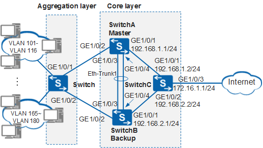
Networking Requirements
Configuration Roadmap
A VRRP group in active/standby mode is used to implement gateway backup. The configuration roadmap is as follows:
Assign an IP address to each interface and configure a routing protocol to ensure network connectivity.
Configure VLAN aggregation on SwitchA and SwitchB to implement Layer 2 isolation and Layer 3 connectivity of VLANs 101 to 180 and save IP addresses.
Create an Eth-Trunk on SwitchA and SwitchB and add member interfaces to the Eth-Trunk to increase the link bandwidth and implement link backup.
Configure a VRRP group between SwitchA and SwitchB. Set a higher priority for SwitchA so that SwitchA functions as the master to forward traffic, and set the preemption delay to 20s on SwitchA. Set a lower priority for SwitchB so that SwitchB functions as the backup.
Associate VRRP with GE1/0/1 and GE1/0/2 on SwitchA so that the VRRP group can detect the fault of the master and perform an active/standby switchover immediately.
SwitchA and SwitchB are core switches, and the switch is an aggregation switch.
Procedure
- Configure devices to ensure network connectivity.
# Assign an IP address to each interface on core devices. SwitchA is used as an example. The configuration of SwitchB is similar to the configuration of SwitchA, and is not mentioned here. For details, see the configuration files.
<HUAWEI> system-view
[HUAWEI] sysname SwitchA
[SwitchA] vlan batch 11 to 15 101 to 180 301 to 305 400
[SwitchA] interface gigabitethernet 1/0/1
[SwitchA-GigabitEthernet1/0/1] port link-type trunk
[SwitchA-GigabitEthernet1/0/1] undo port trunk allow-pass vlan 1
[SwitchA-GigabitEthernet1/0/1] port trunk allow-pass vlan 400
[SwitchA-GigabitEthernet1/0/1] quit
[SwitchA] interface gigabitethernet 1/0/2
[SwitchA-GigabitEthernet1/0/2] port link-type trunk
[SwitchA-GigabitEthernet1/0/2] undo port trunk allow-pass vlan 1
[SwitchA-GigabitEthernet1/0/2] port trunk allow-pass vlan 101 to 180
[SwitchA-GigabitEthernet1/0/2] quit
[SwitchA] interface vlanif 11
[SwitchA-Vlanif11] ip address 10.1.1.2 24
[SwitchA-Vlanif11] quit
[SwitchA] interface vlanif 12
[SwitchA-Vlanif12] ip address 10.1.2.2 24
[SwitchA-Vlanif12] quit
[SwitchA] interface vlanif 13
[SwitchA-Vlanif13] ip address 10.1.3.2 24
[SwitchA-Vlanif13] quit
[SwitchA] interface vlanif 14
[SwitchA-Vlanif14] ip address 10.1.4.2 24
[SwitchA-Vlanif14] quit
[SwitchA] interface vlanif 15
[SwitchA-Vlanif15] ip address 10.1.5.2 24
[SwitchA-Vlanif15] quit
[SwitchA] interface vlanif 400
[SwitchA-Vlanif400] ip address 192.168.1.1 24
[SwitchA-Vlanif400] quit
# Configure Layer 2 transparent transmission on the switch.
<HUAWEI> system-view
[HUAWEI] sysname Switch
[Switch] vlan batch 11 to 15 101 to 180
[Switch] interface gigabitethernet 1/0/1
[Switch-GigabitEthernet1/0/1] port link-type trunk
[Switch-GigabitEthernet1/0/1] undo port trunk allow-pass vlan 1
[Switch-GigabitEthernet1/0/1] port trunk allow-pass vlan 11 to 15 101 to 180
[Switch-GigabitEthernet1/0/1] quit
[Switch] interface gigabitethernet 1/0/2
[Switch-GigabitEthernet1/0/2] port link-type trunk
[Switch-GigabitEthernet1/0/2] undo port trunk allow-pass vlan 1
[Switch-GigabitEthernet1/0/2] port trunk allow-pass vlan 11 to 15 101 to 180
[Switch-GigabitEthernet1/0/2] quit
# Configure OSPF on SwitchA, SwitchB, and switch. SwitchA is used as an example. The configurations of SwitchB and SwitchC are similar to the configuration of SwitchA, and are not mentioned here. For details, see the configuration files.
[SwitchA] ospf 1
[SwitchA-ospf-1] area 0
[SwitchA-ospf-1-area-0.0.0.0] network 10.1.1.0 0.0.0.255
[SwitchA-ospf-1-area-0.0.0.0] network 10.1.2.0 0.0.0.255
[SwitchA-ospf-1-area-0.0.0.0] network 10.1.3.0 0.0.0.255
[SwitchA-ospf-1-area-0.0.0.0] network 10.1.4.0 0.0.0.255
[SwitchA-ospf-1-area-0.0.0.0] network 10.1.5.0 0.0.0.255
[SwitchA-ospf-1-area-0.0.0.0] network 192.168.1.0 0.0.0.255
[SwitchA-ospf-1-area-0.0.0.0] quit
[SwitchA-ospf-1] quit
- Configure a super-VLAN on SwitchA and SwitchB.
# Configure a super-VLAN on SwitchA. The configuration of SwitchB is similar to the configuration of SwitchA, and is not mentioned here. For details, see the configuration files.
[SwitchA] vlan 11
[SwitchA-vlan11] aggregate-vlan
[SwitchA-vlan11] access-vlan 101 to 116 301
[SwitchA-vlan11] quit
[SwitchA] vlan 12
[SwitchA-vlan12] aggregate-vlan
[SwitchA-vlan12] access-vlan 117 to 132 302
[SwitchA-vlan12] quit
[SwitchA] vlan 13
[SwitchA-vlan13] aggregate-vlan
[SwitchA-vlan13] access-vlan 133 to 148 303
[SwitchA-vlan13] quit
[SwitchA] vlan 14
[SwitchA-vlan14] aggregate-vlan
[SwitchA-vlan14] access-vlan 149 to 164 304
[SwitchA-vlan14] quit
[SwitchA] vlan 15
[SwitchA-vlan15] aggregate-vlan
[SwitchA-vlan15] access-vlan 165 to 180 305
[SwitchA-vlan15] quit
- Configure link aggregation on SwitchA and SwitchB.
# Create Eth-Trunk 1 in LACP mode on SwitchA. The configuration of SwitchB is similar to the configuration of SwitchA, and is not mentioned here. For details, see the configuration files.
[SwitchA] interface eth-trunk 1
[SwitchA-Eth-Trunk1] mode lacp
[SwitchA-Eth-Trunk1] port link-type trunk
[SwitchA-Eth-Trunk1] undo port trunk allow-pass vlan 1
[SwitchA-Eth-Trunk1] port trunk allow-pass vlan 301 to 305
[SwitchA-Eth-Trunk1] quit
# Add member interfaces on SwitchA to Eth-Trunk 1. The configuration of SwitchB is similar to the configuration of SwitchA, and is not mentioned here. For details, see the configuration files.
[SwitchA] interface gigabitethernet 1/0/3
[SwitchA-GigabitEthernet1/0/3] eth-trunk 1
[SwitchA-GigabitEthernet1/0/3] quit
[SwitchA] interface gigabitethernet 1/0/4
[SwitchA-GigabitEthernet1/0/4] eth-trunk 1
[SwitchA-GigabitEthernet1/0/4] quit
- Configure VRRP groups on SwitchA and SwitchB.
# Configure a VRRP group on SwitchA, and set the priority of SwitchA to 120 and the preemption delay to 20s.
[SwitchA] interface vlanif 11
[SwitchA-Vlanif11] vrrp vrid 1 virtual-ip 10.1.1.1
[SwitchA-Vlanif11] vrrp vrid 1 priority 120                                          //The default priority of the device in a VRRP group is 100. Change the priority of the master to be higher than that of the backup.
[SwitchA-Vlanif11] vrrp vrid 1 preempt-mode timer delay 20                           //The device in a VRRP group uses the immediate preemption mode by default. Change the preemption delay of the master to prevent traffic interruptions when the master and backup frequently preempt the bandwidth on an unstable network.
[SwitchA-Vlanif11] vrrp vrid 1 track interface gigabitethernet 1/0/1 reduced 100     //Associate the VRRP group with the uplink interface. Set the decreased priority to ensure that the priority of the backup is higher than the priority of the master. Then an active/standby switchover can be triggered.
[SwitchA-Vlanif11] vrrp vrid 1 track interface gigabitethernet 1/0/2 reduced 100     //Associate the VRRP group with the downlink interface. Set the decreased priority to ensure that the priority of the backup is higher than the priority of the master. Then an active/standby switchover can be triggered.
[SwitchA-Vlanif11] vrrp advertise send-mode 301                                      //Specify VLAN 301 where VRRP packets are transmitted to save the network bandwidth.
[SwitchA-Vlanif11] quit
[SwitchA] interface vlanif 12
[SwitchA-Vlanif12] vrrp vrid 2 virtual-ip 10.1.2.1
[SwitchA-Vlanif12] vrrp vrid 2 priority 120
[SwitchA-Vlanif12] vrrp vrid 2 preempt-mode timer delay 20
[SwitchA-Vlanif12] vrrp vrid 2 track interface gigabitethernet 1/0/1 reduced 100
[SwitchA-Vlanif12] vrrp vrid 2 track interface gigabitethernet 1/0/2 reduced 100
[SwitchA-Vlanif12] vrrp advertise send-mode 302
[SwitchA-Vlanif12] quit
[SwitchA] interface vlanif 13
[SwitchA-Vlanif13] vrrp vrid 3 virtual-ip 10.1.3.1
[SwitchA-Vlanif13] vrrp vrid 3 priority 120
[SwitchA-Vlanif13] vrrp vrid 3 preempt-mode timer delay 20
[SwitchA-Vlanif13] vrrp vrid 3 track interface gigabitethernet 1/0/1 reduced 100
[SwitchA-Vlanif13] vrrp vrid 3 track interface gigabitethernet 1/0/2 reduced 100
[SwitchA-Vlanif13] vrrp advertise send-mode 303
[SwitchA-Vlanif13] quit
[SwitchA] interface vlanif 14
[SwitchA-Vlanif14] vrrp vrid 4 virtual-ip 10.1.4.1
[SwitchA-Vlanif14] vrrp vrid 4 priority 120
[SwitchA-Vlanif14] vrrp vrid 4 preempt-mode timer delay 20
[SwitchA-Vlanif14] vrrp vrid 4 track interface gigabitethernet 1/0/1 reduced 100
[SwitchA-Vlanif14] vrrp vrid 4 track interface gigabitethernet 1/0/2 reduced 100
[SwitchA-Vlanif14] vrrp advertise send-mode 304
[SwitchA-Vlanif14] quit
[SwitchA] interface vlanif 15
[SwitchA-Vlanif15] vrrp vrid 5 virtual-ip 10.1.5.1
[SwitchA-Vlanif15] vrrp vrid 5 priority 120
[SwitchA-Vlanif15] vrrp vrid 5 preempt-mode timer delay 20
[SwitchA-Vlanif15] vrrp vrid 5 track interface gigabitethernet 1/0/1 reduced 100
[SwitchA-Vlanif15] vrrp vrid 5 track interface gigabitethernet 1/0/2 reduced 100
[SwitchA-Vlanif15] vrrp advertise send-mode 305
[SwitchA-Vlanif15] quit
# Configure a VRRP group on SwitchB. SwitchB uses the default priority of 100.
[SwitchB] interface vlanif 11
[SwitchB-Vlanif11] vrrp vrid 1 virtual-ip 10.1.1.1
[SwitchB-Vlanif11] vrrp advertise send-mode 301
[SwitchB-Vlanif11] quit
[SwitchB] interface vlanif 12
[SwitchB-Vlanif12] vrrp vrid 2 virtual-ip 10.1.2.1
[SwitchB-Vlanif12] vrrp advertise send-mode 302
[SwitchB-Vlanif12] quit
[SwitchB] interface vlanif 13
[SwitchB-Vlanif13] vrrp vrid 3 virtual-ip 10.1.3.1
[SwitchB-Vlanif13] vrrp advertise send-mode 303
[SwitchB-Vlanif13] quit
[SwitchB] interface vlanif 14
[SwitchB-Vlanif14] vrrp vrid 4 virtual-ip 10.1.4.1
[SwitchB-Vlanif14] vrrp advertise send-mode 304
[SwitchB-Vlanif14] quit
[SwitchB] interface vlanif 15
[SwitchB-Vlanif15] vrrp vrid 5 virtual-ip 10.1.5.1
[SwitchB-Vlanif15] vrrp advertise send-mode 305
[SwitchB-Vlanif15] quit
- Disable STP on SwitchA, SwitchB,
SwitchC, and Switch.
# Disable global STP on SwitchA, SwitchB, SwitchC, and Switch. SwitchA is used as an example. The configurations of SwitchB, SwitchC, and the switch are similar to the configuration of SwitchA, and are not mentioned here. For details, see the configuration files.
[SwitchA] stp disable
Warning: The global STP state will be changed. Continue?[Y/N]:y
- Verify the configuration.
# After the configuration is complete, run the display vrrp command on SwitchA. You can see that SwitchA is the master in VRRP group 1. VRRP group 1 is used as an example. Information of other VRRP groups is similar to information of VRRP group 1.
[SwitchA] display vrrp 1
  Vlanif11  | Virtual Router 1
    State : Master
    Virtual IP : 10.1.1.1
    Master IP : 10.1.1.2
    Send VRRP packet to subvlan : 301
    PriorityRun : 120
    PriorityConfig : 120
    MasterPriority : 120
    Preempt : YES   Delay Time : 20 s
    TimerRun : 1 s
    TimerConfig : 1 s
    Auth type : NONE
    Virtual MAC : 0000-5e00-0101
    Check TTL : YES
    Config type : normal-vrrp
    Backup-forward : disabled
    Track IF       : GigabitEthernet1/0/1   Priority reduced : 100
    IF state       : UP
    Track IF       : GigabitEthernet1/0/2   Priority reduced : 100
    IF state       : UP
    Create time : 2012-05-11 11:39:18
    Last change time : 2012-05-26 11:38:58
# Run the display vrrp command on SwitchB. You can see that SwitchB is the backup. VRRP group 1 is used as an example.
[SwitchB] display vrrp 1
  Vlanif11  | Virtual Router 1
    State : Backup
    Virtual IP : 10.1.1.1
    Master IP : 10.1.1.2
    Send VRRP packet to subvlan : 301
    PriorityRun : 100
    PriorityConfig : 100
    MasterPriority : 120
    Preempt : YES   Delay Time : 0 s
    TimerRun : 1 s
    TimerConfig : 1 s
    Auth type : NONE
    Virtual MAC : 0000-5e00-0101
    Check TTL : YES
    Config type : normal-vrrp
    Backup-forward : disabled
    Create time : 2012-05-11 11:39:18
    Last change time : 2012-05-26 11:38:58
# Run the shutdown command on GE1/0/1 of SwitchA to simulate a link fault. Then run the display vrrp command on SwitchA and SwitchB. You can see that SwitchA is in Backup state, SwitchB enters the Master state, and the associated interface becomes Down.
[SwitchA] interface gigabitethernet 1/0/1
[SwitchA-GigabitEthernet1/0/1] shutdown
[SwitchA-GigabitEthernet1/0/1] quit
[SwitchA] display vrrp 1
  Vlanif11  | Virtual Router 1
    State : Backup
    Virtual IP : 10.1.1.1
    Master IP : 10.1.1.3
    Send VRRP packet to subvlan : 301
    PriorityRun : 20
    PriorityConfig : 120
    MasterPriority : 100
    Preempt : YES   Delay Time : 20 s
    TimerRun : 1 s
    TimerConfig : 1 s
    Auth type : NONE
    Virtual MAC : 0000-5e00-0101
    Check TTL : YES
    Config type : normal-vrrp
    Backup-forward : disabled
    Track IF       : GigabitEthernet1/0/1   Priority reduced : 100
    IF state       : DOWN
    Track IF       : GigabitEthernet1/0/2   Priority reduced : 100
    IF state       : UP
    Create time : 2012-05-11 11:39:18
    Last change time : 2012-05-26 14:12:38
[SwitchB] display vrrp 1 Vlanif11 | Virtual Router 1 State : Master Virtual IP : 10.1.1.1 Master IP : 10.1.1.3 Send VRRP packet to subvlan : 301 PriorityRun : 100 PriorityConfig : 100 MasterPriority : 100 Preempt : YES Delay Time : 0 s TimerRun : 1 s TimerConfig : 1 s Auth type : NONE Virtual MAC : 0000-5e00-0101 Check TTL : YES Config type : normal-vrrp Backup-forward : disabled Create time : 2012-05-11 11:39:18 Last change time : 2012-05-26 14:12:38# Run the undo shutdown command on GE1/0/1 of SwitchA.
[SwitchA] interface gigabitethernet 1/0/1
[SwitchA-GigabitEthernet1/0/1] undo shutdown
[SwitchA-GigabitEthernet1/0/1] quit
# After 20s, run the display vrrp command on SwitchA and SwitchB. You can see that SwitchA is restored as the master and SwitchB is restored as the backup, and the associated interface is in Up state.
[SwitchA] display vrrp 1
  Vlanif11  | Virtual Router 1
    State : Master
    Virtual IP : 10.1.1.1
    Master IP : 10.1.1.2
    Send VRRP packet to subvlan : 301
    PriorityRun : 120
    PriorityConfig : 120
    MasterPriority : 120
    Preempt : YES   Delay Time : 20 s
    TimerRun : 1 s
    TimerConfig : 1 s
    Auth type : NONE
    Virtual MAC : 0000-5e00-0101
    Check TTL : YES
    Config type : normal-vrrp
    Backup-forward : disabled
    Track IF       : GigabitEthernet1/0/1   Priority reduced : 100
    IF state       : UP
    Track IF       : GigabitEthernet1/0/2   Priority reduced : 100
    IF state       : UP
    Create time : 2012-05-11 11:39:18
    Last change time : 2012-05-26 14:17:36
[SwitchB] display vrrp 1 Vlanif11 | Virtual Router 1 State : Backup Virtual IP : 10.1.1.1 Master IP : 10.1.1.2 Send VRRP packet to subvlan : 301 PriorityRun : 100 PriorityConfig : 100 MasterPriority : 120 Preempt : YES Delay Time : 0 s TimerRun : 1 s TimerConfig : 1 s Auth type : NONE Virtual MAC : 0000-5e00-0101 Check TTL : YES Config type : normal-vrrp Backup-forward : disabled Create time : 2012-05-11 11:39:18 Last change time : 2012-05-26 14:17:36
Configuration Files
-
# sysname SwitchA # vlan batch 11 to 15 101 to 180 301 to 305 400 # stp disable # vlan 11 aggregate-vlan access-vlan 101 to 116 301 vlan 12 aggregate-vlan access-vlan 117 to 132 302 vlan 13 aggregate-vlan access-vlan 133 to 148 303 vlan 14 aggregate-vlan access-vlan 149 to 164 304 vlan 15 aggregate-vlan access-vlan 165 to 180 305 # interface Vlanif11 ip address 10.1.1.2 255.255.255.0 vrrp vrid 1 virtual-ip 10.1.1.1 vrrp vrid 1 priority 120 vrrp vrid 1 preempt-mode timer delay 20 vrrp vrid 1 track interface gigabitethernet1/0/1 reduced 100 vrrp vrid 1 track interface gigabitethernet1/0/2 reduced 100 vrrp advertise send-mode 301 # interface Vlanif12 ip address 10.1.2.2 255.255.255.0 vrrp vrid 2 virtual-ip 10.1.2.1 vrrp vrid 2 priority 120 vrrp vrid 2 preempt-mode timer delay 20 vrrp vrid 2 track interface gigabitethernet1/0/1 reduced 100 vrrp vrid 2 track interface gigabitethernet1/0/2 reduced 100 vrrp advertise send-mode 302 # interface Vlanif13 ip address 10.1.3.2 255.255.255.0 vrrp vrid 3 virtual-ip 10.1.3.1 vrrp vrid 3 priority 120 vrrp vrid 3 preempt-mode timer delay 20 vrrp vrid 3 track interface gigabitethernet1/0/1 reduced 100 vrrp vrid 3 track interface gigabitethernet1/0/2 reduced 100 vrrp advertise send-mode 303 # interface Vlanif14 ip address 10.1.4.2 255.255.255.0 vrrp vrid 4 virtual-ip 10.1.4.1 vrrp vrid 4 priority 120 vrrp vrid 4 preempt-mode timer delay 20 vrrp vrid 4 track interface gigabitethernet1/0/1 reduced 100 vrrp vrid 4 track interface gigabitethernet1/0/2 reduced 100 vrrp advertise send-mode 304 # interface Vlanif15 ip address 10.1.5.2 255.255.255.0 vrrp vrid 5 virtual-ip 10.1.5.1 vrrp vrid 5 priority 120 vrrp vrid 5 preempt-mode timer delay 20 vrrp vrid 5 track interface gigabitethernet1/0/1 reduced 100 vrrp vrid 5 track interface gigabitethernet1/0/2 reduced 100 vrrp advertise send-mode 305 # interface Vlanif400 ip address 192.168.1.1 255.255.255.0 # interface Eth-Trunk1 port link-type trunk undo port trunk allow-pass vlan 1 port trunk allow-pass vlan 301 to 305 mode lacp # interface GigabitEthernet1/0/1 port link-type trunk undo port trunk allow-pass vlan 1 port trunk allow-pass vlan 400 # interface GigabitEthernet1/0/2 port link-type trunk undo port trunk allow-pass vlan 1 port trunk allow-pass vlan 101 to 180 # interface GigabitEthernet1/0/3 eth-trunk 1 # interface GigabitEthernet1/0/4 eth-trunk 1 # ospf 1 area 0.0.0.0 network 10.1.1.0 0.0.0.255 network 10.1.2.0 0.0.0.255 network 10.1.3.0 0.0.0.255 network 10.1.4.0 0.0.0.255 network 10.1.5.0 0.0.0.255 network 192.168.1.0 0.0.0.255 # return -
# sysname SwitchB # vlan batch 11 to 15 101 to 180 200 301 to 305 # stp disable # vlan 11 aggregate-vlan access-vlan 101 to 116 301 vlan 12 aggregate-vlan access-vlan 117 to 132 302 vlan 13 aggregate-vlan access-vlan 133 to 148 303 vlan 14 aggregate-vlan access-vlan 149 to 164 304 vlan 15 aggregate-vlan access-vlan 165 to 180 305 # interface Vlanif11 ip address 10.1.1.3 255.255.255.0 vrrp vrid 1 virtual-ip 10.1.1.1 vrrp advertise send-mode 301 # interface Vlanif12 ip address 10.1.2.3 255.255.255.0 vrrp vrid 2 virtual-ip 10.1.2.1 vrrp advertise send-mode 302 # interface Vlanif13 ip address 10.1.3.3 255.255.255.0 vrrp vrid 3 virtual-ip 10.1.3.1 vrrp advertise send-mode 303 # interface Vlanif14 ip address 10.1.4.3 255.255.255.0 vrrp vrid 4 virtual-ip 10.1.4.1 vrrp advertise send-mode 304 # interface Vlanif15 ip address 10.1.5.3 255.255.255.0 vrrp vrid 5 virtual-ip 10.1.5.1 vrrp advertise send-mode 305 # interface Vlanif200 ip address 192.168.2.1 255.255.255.0 # interface Eth-Trunk1 port link-type trunk undo port trunk allow-pass vlan 1 port trunk allow-pass vlan 301 to 305 mode lacp # interface GigabitEthernet1/0/1 port link-type trunk undo port trunk allow-pass vlan 1 port trunk allow-pass vlan 200 # interface GigabitEthernet1/0/2 port link-type trunk undo port trunk allow-pass vlan 1 port trunk allow-pass vlan 101 to 180 # interface GigabitEthernet1/0/3 eth-trunk 1 # interface GigabitEthernet1/0/4 eth-trunk 1 # ospf 1 area 0.0.0.0 network 10.1.1.0 0.0.0.255 network 10.1.2.0 0.0.0.255 network 10.1.3.0 0.0.0.255 network 10.1.4.0 0.0.0.255 network 10.1.5.0 0.0.0.255 network 192.168.2.0 0.0.0.255 # return -
#
sysname SwitchC
#
vlan batch 200 300 400
#
stp disable
#
interface Vlanif200
 ip address 192.168.2.2 255.255.255.0
#
interface Vlanif300
 ip address 172.16.1.1 255.255.255.0
#
interface Vlanif400
 ip address 192.168.1.2 255.255.255.0
#
interface GigabitEthernet1/0/1
 port link-type trunk
 undo port trunk allow-pass vlan 1
 port trunk allow-pass vlan 400
#
interface GigabitEthernet1/0/2
 port link-type trunk
 undo port trunk allow-pass vlan 1
 port trunk allow-pass vlan 200
#
interface GigabitEthernet1/0/3
 port link-type trunk
 undo port trunk allow-pass vlan 1
 port trunk allow-pass vlan 300
#
ospf 1
 area 0.0.0.0
  network 172.16.1.0 0.0.0.255
  network 192.168.1.0 0.0.0.255
  network 192.168.2.0 0.0.0.255
#
return
Configuration file of the switch
#
sysname Switch
#
vlan batch 11 to 15 101 to 180
#
stp disable
#
interface GigabitEthernet1/0/1
 port link-type trunk
 undo port trunk allow-pass vlan 1
 port trunk allow-pass vlan 11 to 15 101 to 180
#
interface GigabitEthernet1/0/2
 port link-type trunk
 undo port trunk allow-pass vlan 1
 port trunk allow-pass vlan 11 to 15 101 to 180
#
return
Applicable Product Models and Versions
Product |
Product Model |
Software Version |
|---|---|---|
S2700 |
S2720-EI |
V200R011C10, V200R012C00, V200R013C00, V200R019C00, V200R019C10 |
S3700 |
S3700-EI |
V100R006C05 |
S3700-HI |
V200R001C00 |
|
S5700 |
S5720-LI, S5720S-LI |
V200R010C00, V200R011C00, V200R011C10, V200R012(C00&C20), V200R013C00, V200R019C00, V200R019C10 |
S5720-SI, S5720S-SI |
V200R008C00, V200R009C00, V200R010C00, V200R011C00, V200R011C10, V200R012C00, V200R013C00, V200R019C00, V200R019C10 |
|
S5720I-SI |
V200R012C00, V200R013C00, V200R019C00, V200R019C10 |
|
S5700-EI |
V200R001(C00&C01), V200R002C00, V200R003C00, V200R005(C00&C01&C02&C03) |
|
S5700-HI |
V200R001(C00&C01), V200R002C00, V200R003C00, V200R005(C00SPC500&C01&C02) |
|
S5710-EI |
V200R001C00, V200R002C00, V200R003C00, V200R005(C00&C02) |
|
S5720-EI |
V200R007C00, V200R008C00, V200R009C00, V200R010C00, V200R011C00, V200R011C10, V200R012C00, V200R013C00, V200R019C00, V200R019C10 |
|
S5710-HI |
V200R003C00, V200R005(C00&C02&C03) |
|
S5720-HI |
V200R006C00, V200R007(C00&C10), V200R008C00, V200R009C00, V200R010C00, V200R011C00, V200R011C10, V200R012C00, V200R013C00, V200R019C00, V200R019C10 |
|
S5730-HI |
V200R012C00, V200R013C00, V200R019C00, V200R019C10 |
|
S5730-SI |
V200R011C10, V200R012C00, V200R013C00, V200R019C00, V200R019C10 |
|
S5730S-EI |
V200R011C10, V200R012C00, V200R013C00, V200R019C00, V200R019C10 |
|
S5731-H |
V200R013C02, V200R019C00, V200R019C10 |
|
S5731-S, S5731S-S |
V200R019C00, V200R019C10 |
|
S5731S-H |
V200R019C00, V200R019C10 |
|
S5732-H |
V200R019C00, V200R019C10 |
|
S5735-L, S5735S-L |
V200R019C00, V200R019C10 |
|
S5735S-L-M |
V200R019C00, V200R019C10 |
|
S5735-S, S5735S-S |
V200R019C00, V200R019C10 |
|
S5700 |
S5735-S-I |
V200R019C10 |
S6700 |
S6720-LI, S6720S-LI |
V200R011C00, V200R011C10, V200R012C00, V200R013C00, V200R019C00, V200R019C10 |
S6720-SI, S6720S-SI |
V200R011C00, V200R011C10, V200R012C00, V200R013C00, V200R019C00, V200R019C10 |
|
S6700-EI |
V200R001(C00&C01), V200R002C00, V200R003C00, V200R005(C00&C01&C02) |
|
S6720-EI |
V200R008C00, V200R009C00, V200R010C00, V200R011C00, V200R011C10, V200R012C00, V200R013C00, V200R019C00, V200R019C10 |
|
S6720S-EI |
V200R009C00, V200R010C00, V200R011C00, V200R011C10, V200R012C00, V200R013C00, V200R019C00, V200R019C10 |
|
S6720-HI |
V200R012C00, V200R013C00, V200R019C00, V200R019C10 |
|
S6730-H |
V200R013C02, V200R019C00, V200R019C10 |
|
S6730S-H |
V200R019C10 |
|
S6730-S, S6730S-S |
V200R019C00, V200R019C10 |
|
S7700 |
S7703, S7706, S7712 |
V200R001(C00&C01), V200R002C00, V200R003C00, V200R005C00, V200R006C00, V200R007C00, V200R008C00, V200R009C00, V200R010C00, V200R011C10, V200R012C00, V200R013C00, V200R013C02, V200R019C00, V200R019C10 |
S7703 PoE |
V200R013C00, V200R019C00, V200R019C10 |
|
S7706 PoE |
V200R013C00, V200R019C00, V200R019C10 |
|
S9700 |
S9703, S9706, S9712 |
V200R001(C00&C01), V200R002C00, V200R003C00, V200R005C00, V200R006C00, V200R007(C00&C10), V200R008C00, V200R009C00, V200R010C00, V200R011C10, V200R012C00, V200R013C00 |