Example for Configuring WLAN Services for a Wireless City Project (AC Bypass Deployment, Portal Authentication)
WLAN Service Overview
You can configure WLAN services to allow wireless users to easily access a wireless network and move around within its coverage area.
Configuration Notes
For details about common WLAN configuration notes, see General Precautions for WLAN. For more deployment and configuration suggestions, see Wireless Network Deployment and Configuration Suggestions.
Configure a proper RADIUS packet retransmission timeout interval.
For a large-scale or busy network, configure the shortest retransmission timeout interval for RADIUS request packets. When a long retransmission timeout interval is set, retransmission occupies system resources. A short retransmission timeout interval can improve the AC's packet processing capability.
The default retransmission timeout interval for wireless users is 5 seconds, which is suitable for most wireless user authentication scenarios. When IP addresses of more than eight authentication servers are configured in a RADIUS server template, or 802.1X authentication is used, it is recommended that the retransmission timeout interval be set to 1 second to improve network processing efficiency.
- Select an inter-card or inter-chassis interface as a member interface of the Eth-Trunk to improve interface reliability.
From V200R011C10, WLAN configurations are automatically delivered, without the need of running the commit all command.
- In this example, Portal authentication is used. To ensure network security, configure an appropriate security policy according to service requirements.
In direct forwarding mode, configure port isolation on the interface directly connected to APs. If port isolation is not configured, many broadcast packets will be transmitted in the VLANs or WLAN users on different APs can directly communicate at Layer 2.
- Configure the management VLAN and service VLAN:
- In tunnel forwarding mode, service packets are encapsulated in a CAPWAP tunnel and forwarded to the AC. The AC then forwards the packets to the upper-layer network. Service packets and management packets can be forwarded normally only if the network between the AC and APs is added to the management VLAN and the network between the AC and upper-layer network is added to the service VLAN.
- In direct forwarding mode, service packets are not encapsulated into a CAPWAP tunnel, but are directly forwarded to the upper-layer network. Service packets and management packets can be forwarded normally only if the network between APs and upper-layer network is added to the service VLAN and the network between the AC and APs is added to the management VLAN.
- No ACK mechanism is provided for multicast packet transmission on air interfaces. In addition, wireless links are unstable. To ensure stable transmission of multicast packets, they are usually sent at low rates. If a large number of such multicast packets are sent from the network side, the air interfaces may be congested. You are advised to configure multicast packet suppression to reduce impact of a large number of low-rate multicast packets on the wireless network. Exercise caution when configuring the rate limit; otherwise, the multicast services may be affected.
- In direct forwarding mode, you are advised to configure multicast packet suppression on switch interfaces connected to APs.
- In tunnel forwarding mode, you are advised to configure multicast packet suppression in traffic profiles of the AC.
Networking Requirements
A city needs to deploy the wireless smart city project and requires that Portal authentication be used for wireless users. Due to the large number of wireless users, high wireless service performance and Portal authentication performance are required.
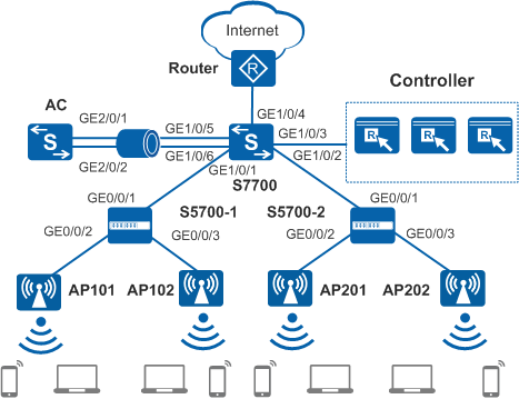
As shown in Figure 1, the core switch S7700 functions as the gateway for STAs and APs and as a DHCP server to assign IP addresses to STAs and APs. The S7700 connects to APs through PoE access switches S5700-1 and S5700-2. The AC and APs are located on a Layer 3 network. The AC is the X series card on the S7700 and connected to the S7700 through Eth-Trunk in bypass mode.
To facilitate network planning and management, the access switches are only used to transparently transmit data at Layer 2.
The following uses an AC running V200R009C00 as an example. The key configurations vary in different versions. For details, see the Command Reference in the actual version.
Data Planning
Item |
Interface |
VLAN |
Description |
|---|---|---|---|
AC |
Eth-Trunk1 |
100 |
Configured to improve network bandwidth and reliability Add GE2/0/1 and GE2/0/2 to Eth-Trunk 1 and connect the two interfaces to the S7700. |
S5700-1 |
GE0/0/1 |
10, 101 |
Connected to the AC |
GE0/0/2 |
10, 101 |
Connected to AP101 |
|
GE0/0/3 |
10, 101 |
Connected to AP102 |
|
S5700-2 |
GE0/0/1 |
20, 102 |
Connected to the AC |
GE0/0/2 |
20, 102 |
Connected to AP201 |
|
GE0/0/3 |
20, 102 |
Connected to AP202 |
|
S7700 |
GE1/0/1 |
10, 101 |
Connected to S5700-1 |
GE1/0/2 |
20, 102 |
Connected to S5700-2 |
|
GE1/0/3 |
300 |
Connected to the controller |
|
GE1/0/4 |
101, 102 |
Connected to the upper-layer network |
|
Eth-Trunk1 |
100 |
Configured to improve network bandwidth and reliability Add GE1/0/5 and GE1/0/6 to Eth-Trunk 1 and connect the two interfaces to the AC. |
Item |
Data |
Description |
|---|---|---|
IP address of the AC's source interface |
10.23.100.1/24 |
- |
AP group |
|
- |
|
||
Portal access profile |
|
- |
|
||
Authentication profile |
|
- |
|
||
Regulatory domain profile |
|
- |
RRM profile |
Name: rrm1 |
- |
Radio profile |
|
- |
Security profile |
|
- |
SSID profile |
|
- |
Traffic profile |
Name: traffic1 |
- |
VAP profile |
|
Provides WLAN network coverage for Area 2. |
|
Provides WLAN network coverage for Area 2 |
|
DHCP server |
The S7700 functions as a DHCP server to assign IP addresses to APs and STAs. |
- |
Gateway and IP address pool range of APs |
VLANIF 10: 10.23.10.1/24 10.23.10.2-10.23.10.254/24 |
Gateway and IP address pool for AP101 and AP102 |
VLANIF 20: 10.23.20.1/24 10.23.20.2-10.23.20.254/24 |
Gateway and IP address pool for AP201 and AP202 |
|
Gateway and IP address pool range of STAs |
VLANIF 101: 10.23.101.1/24 10.23.101.2-10.23.101.254/24 |
- |
VLANIF 102: 10.23.102.1/24 10.23.102.2-10.23.102.254/24 |
- |
|
Server parameters |
Authentication server:
|
|
Accounting server:
|
||
Authorization server:
|
||
Portal server:
|
Item |
Data |
Description |
|---|---|---|
AP101 |
Radio 0: channel 1 and power level 10 Radio 1: channel 153 and power level 10 |
Use the WLAN Planner to plan AP installation locations, and the working channel and power of each AP radio. Set the channel mode and power mode to fixed, and configure the channel and power for each AP. |
AP102 |
Radio 0: channel 6 and power level 10 Radio 1: channel 161 and power level 10 |
|
AP201 |
Radio 0: channel 1 and power level 10 Radio 1: channel 153 and power level 10 |
|
AP202 |
Radio 0: channel 6 and power level 10 Radio 1: channel 161 and power level 10 |
Configuration Roadmap
The configuration roadmap is as follows:
- Configure network interworking of the AC, APs, S5700-1, S5700-2, S7700, and other network devices.
- Configure the S7700 as a DHCP server to assign IP addresses to APs and STAs.
- Configure a RADIUS server template, configure authentication, accounting, and authorization in the template, and configure Portal authentication.
- Configure basic WLAN services, including AC system parameters, AP management, and WLAN service parameters.
- Configure VAPs and deliver VAP parameters to APs.
- Verify the configuration to ensure that both wired and wireless users can access the Internet.
Procedure
- Configure network devices to communicate with each other.
# Add GE0/0/1 to GE0/0/3 of S5700-1 to VLAN 10 (management VLAN) and VLAN 101 (service VLAN). Set PVIDs for interfaces directly connected to APs. You are advised to configure port isolation on these interfaces to reduce unnecessary broadcast traffic.
[HUAWEI] sysname S5700-1
[S5700-1] vlan batch 10 101
[S5700-1] interface gigabitethernet 0/0/1
[S5700-1-GigabitEthernet0/0/1] port link-type trunk
[S5700-1-GigabitEthernet0/0/1] port trunk allow-pass vlan 10 101
[S5700-1-GigabitEthernet0/0/1] undo port trunk allow-pass vlan 1
[S5700-1-GigabitEthernet0/0/1] quit
[S5700-1] interface gigabitethernet 0/0/2
[S5700-1-GigabitEthernet0/0/2] port link-type trunk
[S5700-1-GigabitEthernet0/0/2] port trunk allow-pass vlan 10 101
[S5700-1-GigabitEthernet0/0/2] port trunk pvid vlan 10  //Set a PVID for the interface directly connected to the AP.
[S5700-1-GigabitEthernet0/0/2] undo port trunk allow-pass vlan 1
[S5700-1-GigabitEthernet0/0/2] stp edged-port enable
[S5700-1-GigabitEthernet0/0/2] port-isolate enable  //Configure port isolation to reduce broadcast packets.
[S5700-1-GigabitEthernet0/0/2] quit
[S5700-1] interface gigabitethernet 0/0/3
[S5700-1-GigabitEthernet0/0/3] port link-type trunk
[S5700-1-GigabitEthernet0/0/3] port trunk allow-pass vlan 10 101
[S5700-1-GigabitEthernet0/0/3] port trunk pvid vlan 10
[S5700-1-GigabitEthernet0/0/3] undo port trunk allow-pass vlan 1
[S5700-1-GigabitEthernet0/0/3] stp edged-port enable
[S5700-1-GigabitEthernet0/0/3] port-isolate enable
[S5700-1-GigabitEthernet0/0/3] quit
# Add GE0/0/1 to GE0/0/3 of S5700-2 to VLAN 20 (management VLAN) and VLAN 102 (service VLAN). Set PVIDs for interfaces directly connected to APs. You are advised to configure port isolation on these interfaces to reduce unnecessary broadcast traffic.
[HUAWEI] sysname S5700-2
[S5700-2] vlan batch 20 102
[S5700-2] interface gigabitethernet 0/0/1
[S5700-2-GigabitEthernet0/0/1] port link-type trunk
[S5700-2-GigabitEthernet0/0/1] port trunk allow-pass vlan 20 102
[S5700-2-GigabitEthernet0/0/1] undo port trunk allow-pass vlan 1
[S5700-2-GigabitEthernet0/0/1] quit
[S5700-2] interface gigabitethernet 0/0/2
[S5700-2-GigabitEthernet0/0/2] port link-type trunk
[S5700-2-GigabitEthernet0/0/2] port trunk allow-pass vlan 20 102
[S5700-2-GigabitEthernet0/0/2] port trunk pvid vlan 20  //Set a PVID for the interface directly connected to the AP.
[S5700-2-GigabitEthernet0/0/2] undo port trunk allow-pass vlan 1
[S5700-2-GigabitEthernet0/0/2] stp edged-port enable
[S5700-2-GigabitEthernet0/0/2] port-isolate enable  //Configure port isolation to reduce broadcast packets.
[S5700-2-GigabitEthernet0/0/2] quit
[S5700-2] interface gigabitethernet 0/0/3
[S5700-2-GigabitEthernet0/0/3] port link-type trunk
[S5700-2-GigabitEthernet0/0/3] port trunk allow-pass vlan 20 102
[S5700-2-GigabitEthernet0/0/3] port trunk pvid vlan 20
[S5700-2-GigabitEthernet0/0/3] undo port trunk allow-pass vlan 1
[S5700-2-GigabitEthernet0/0/3] stp edged-port enable
[S5700-2-GigabitEthernet0/0/3] port-isolate enable
[S5700-2-GigabitEthernet0/0/3] quit
# On the S7700, add GE1/0/1 (connected to S5700-1) to VLAN 10 and VLAN 101, GE1/0/2 (connected to S5700-2) to VLAN 20 and VLAN 102, GE1/0/3 (connected to the controller) to VLAN 300, GE1/0/4 (connected to the upper-layer network) to VLAN 101 and VLAN 102, and GE1/0/5 and GE1/0/6 (connected to the AC) to Eth-Trunk 1. Add Eth-Trunk 1 to VLAN 100.
[HUAWEI] sysname S7700
[S7700] vlan batch 10 20 100 101 102 300
[S7700] interface gigabitethernet 1/0/1
[S7700-GigabitEthernet1/0/1] port link-type trunk
[S7700-GigabitEthernet1/0/1] port trunk allow-pass vlan 10 101
[S7700-GigabitEthernet1/0/1] undo port trunk allow-pass vlan 1
[S7700-GigabitEthernet1/0/1] quit
[S7700] interface gigabitethernet 1/0/2
[S7700-GigabitEthernet1/0/2] port link-type trunk
[S7700-GigabitEthernet1/0/2] port trunk allow-pass vlan 20 102
[S7700-GigabitEthernet1/0/2] undo port trunk allow-pass vlan 1
[S7700-GigabitEthernet1/0/2] quit
[S7700] interface gigabitethernet 1/0/3
[S7700-GigabitEthernet1/0/3] port link-type trunk
[S7700-GigabitEthernet1/0/3] port trunk allow-pass vlan 300
[S7700-GigabitEthernet1/0/3] undo port trunk allow-pass vlan 1
[S7700-GigabitEthernet1/0/3] quit
[S7700] interface gigabitethernet 1/0/4
[S7700-GigabitEthernet1/0/4] port link-type trunk
[S7700-GigabitEthernet1/0/4] port trunk allow-pass vlan 101 102
[S7700-GigabitEthernet1/0/4] undo port trunk allow-pass vlan 1
[S7700-GigabitEthernet1/0/4] quit
[S7700] interface eth-trunk 1
[S7700-Eth-Trunk1] port link-type trunk
[S7700-Eth-Trunk1] port trunk allow-pass vlan 100
[S7700-Eth-Trunk1] undo port trunk allow-pass vlan 1
[S7700-Eth-Trunk1] trunkport gigabitethernet 1/0/5 1/0/6   //Add GE1/0/5 and GE1/0/6 to Eth-Trunk 1. You are advised to select inter-card or inter-chassis interfaces as member interfaces of the Eth-Trunk to improve interface reliability.
[S7700-Eth-Trunk1] quit
# On the S7700, configure VLANIF 100 for communication with the AC and VLANIF 300 for communication with the controller.
[S7700] interface vlanif100
[S7700-Vlanif100] ip address 10.23.100.10 24  //Configure an IP address for communication between the S7700 and AC.
[S7700-Vlanif100] quit
[S7700] interface vlanif300
[S7700-Vlanif300] ip address 10.23.30.10 24  //Configure an IP address for communication between the S7700 and controller.
[S7700-Vlanif300] quit
# On the AC, add GE2/0/1 and GE2/0/2 connected to the S7700 to Eth-Trunk 1 and add Eth-Trunk 1 to VLAN 100.
[HUAWEI] sysname AC
[AC] vlan batch 100
[AC] interface eth-trunk 1
[AC-Eth-Trunk1] port link-type trunk
[AC-Eth-Trunk1] port trunk allow-pass vlan 100
[AC-Eth-Trunk1] undo port trunk allow-pass vlan 1
[AC-Eth-Trunk1] trunkport gigabitethernet 2/0/1 2/0/2  //Add GE2/0/1 and GE2/0/2 to Eth-Trunk1. You are advised to select inter-card or inter-chassis interfaces as member interfaces of the Eth-Trunk to improve interface reliability.
[AC-Eth-Trunk1] quit
# Configure VLANIF 100 on the AC for communication with the S7700.
[AC] interface vlanif100 [AC-Vlanif100] ip address 10.23.100.1 24 //Configure an IP address for communication between the S7700 and AC. [AC-Vlanif100] quit - Configure the S7700 as a DHCP server to assign IP addresses to APs and STAs.
# Configure the S7700 to assign IP addresses to the STAs and APs from the global address pool.
 Configure the DNS server as required. The common methods are as follows:
- In interface address pool scenarios, run the dhcp server dns-list ip-address &<1-8> command in the VLANIF interface view.
- In global address pool scenarios, run the dns-list ip-address &<1-8> command in the IP address pool view.
[S7700] dhcp enable
[S7700] interface vlanif 10  //Configure a global address pool to assign IP addresses to AP101 and AP102.
[S7700-Vlanif10] description manage_ap1
[S7700-Vlanif10] ip address 10.23.10.1 24
[S7700-Vlanif10] dhcp select global
[S7700-Vlanif10] quit
[S7700] ip pool manage_ap1
[S7700-ip-pool-manage_ap1] gateway-list 10.23.10.1
[S7700-ip-pool-manage_ap1] network 10.23.10.0 mask 255.255.255.0
[S7700-ip-pool-manage_ap1] option 43 sub-option 2 ip-address 10.23.100.1  //Since a Layer 3 network is deployed between the AC and APs, configure Option43 to advertise the AC's IP address to APs.
[S7700-ip-pool-manage_ap1] quit
[S7700] interface vlanif 20  //Configure a global address pool to assign IP addresses to AP201 and AP202.
[S7700-Vlanif20] description manage_ap2
[S7700-Vlanif20] ip address 10.23.20.1 24
[S7700-Vlanif20] dhcp select global
[S7700-Vlanif20] quit
[S7700] ip pool manage_ap2
[S7700-ip-pool-manage_ap2] gateway-list 10.23.20.1
[S7700-ip-pool-manage_ap2] network 10.23.20.0 mask 255.255.255.0
[S7700-ip-pool-manage_ap2] option 43 sub-option 2 ip-address 10.23.100.1  //Since a Layer 3 network is deployed between the AC and APs, configure Option 43 to advertise the AC's IP address to the APs.
[S7700-ip-pool-manage_ap2] quit
[S7700] interface vlanif 101  //Configure a global IP address pool to assign IP addresses to STAs connected to AP101 and AP102.
[S7700-Vlanif101] description manage_area1_sta
[S7700-Vlanif101] ip address 10.23.101.1 24
[S7700-Vlanif101] dhcp select global
[S7700-Vlanif101] quit
[S7700] ip pool manage_area1_sta
[S7700-ip-pool-manage_area1_sta] gateway-list 10.23.101.1
[S7700-ip-pool-manage_area1_sta] network 10.23.101.0 mask 255.255.255.0
[S7700-ip-pool-manage_area1_sta] quit
[S7700] interface vlanif 102  //Configure a global IP address pool to assign IP addresses to STAs connected to AP201 and AP202.
[S7700-Vlanif102] description manage_area2_sta
[S7700-Vlanif102] ip address 10.23.102.1 24
[S7700-Vlanif102] dhcp select global
[S7700-Vlanif102] quit
[S7700] ip pool manage_area2_sta
[S7700-ip-pool-manage_area2_sta] gateway-list 10.23.102.1
[S7700-ip-pool-manage_area2_sta] network 10.23.102.0 mask 255.255.255.0
[S7700-ip-pool-manage_area2_sta] quit
# Configure a default route to the S7700 on the AC.
[AC] ip route-static 0.0.0.0 0.0.0.0 10.23.100.10
- Configure a RADIUS server template, configure authentication, accounting, and authorization in the template, and configure Portal authentication.
# Configure a RADIUS server template on the AC, and configure authentication, accounting, and authorization in the template.
[AC] radius-server template radius1  //Create the RADIUS server template radius1.
[AC-radius-radius1] radius-server authentication 10.23.30.1 1812 source ip-address 10.23.100.1 weight 80   //Configure the active RADIUS authentication server 1 and authentication port 1812. The AC uses the IP address 10.23.100.1 to communicate with the active RADIUS authentication server 1.
[AC-radius-radius1] radius-server authentication 10.23.30.2 1812 source ip-address 10.23.100.1 weight 80   //Configure the active RADIUS authentication server 2 and authentication port 1812. The AC uses the IP address 10.23.100.1 to communicate with the active RADIUS authentication server 2.
[AC-radius-radius1] radius-server authentication 10.23.30.3 1812 source ip-address 10.23.100.1 weight 20   //Configure the standby RADIUS authentication server, with the weight value lower than the active authentication server. Set the authentication port number to 1812. The AC uses the IP address 10.23.100.1 to communicate with the standby RADIUS authentication server.
[AC-radius-radius1] radius-server accounting 10.23.30.1 1813 source ip-address 10.23.100.1 weight 80   //Configure the active RADIUS accounting server 1 to collect user login and logout information and set the accounting port number to 1813. The AC uses the IP address 10.23.100.1 to communicate with the active RADIUS accounting server 1.
[AC-radius-radius1] radius-server accounting 10.23.30.2 1813 source ip-address 10.23.100.1 weight 80   //Configure the active RADIUS accounting server 2 to collect user login and logout information and set the accounting port number to 1813. The AC uses the IP address 10.23.100.1 to communicate with the active RADIUS accounting server 2.
[AC-radius-radius1] radius-server accounting 10.23.30.3 1813 source ip-address 10.23.100.1 weight 20   //Configure the standby RADIUS accounting server, with the weight value lower than the active accounting server. Set the accounting port number to 1813. The AC uses the IP address 10.23.100.1 to communicate with the standby RADIUS accounting server.
[AC-radius-radius1] radius-server shared-key cipher Admin@123   //Configure a shared key for the RADIUS server.
[AC-radius-radius1] radius-server detect-server interval 30   //Set the RADIUS automatic detection interval to 30s. The default value is 60s.
[AC-radius-radius1] quit
[AC] aaa
[AC-aaa] authentication-scheme radius1  //Create the authentication scheme radius1.
[AC-aaa-authen-radius1] authentication-mode radius   //If the controller functions as the RADIUS server, the authentication mode must be set to RADIUS.
[AC-aaa-authen-radius1] quit
[AC-aaa] accounting-scheme radius1  //Create the accounting scheme radius 1.
[AC-aaa-accounting-radius1] accounting-mode radius   //Set the accounting mode to RADIUS. To facilitate account status information maintenance on the RADIUS server, including the login and logout information, and forced logout information, the accounting mode must be set to radius.
[AC-aaa-accounting-radius1] accounting realtime 15   //Enable real-time accounting and set the accounting interval to 15 minutes. By default, real-time accounting is disabled.
[AC-aaa-accounting-radius1] quit
[AC-aaa] domain portal1   //Create the domain portal1.
[AC-aaa-domain-portal1] authentication-scheme radius1  //Bind the authentication scheme radius1.
[AC-aaa-domain-portal1] accounting-scheme radius1  //Bind the accounting scheme radius1.
[AC-aaa-domain-portal1] radius-server radius1  //Bind the RADIUS server template radius1.
[AC-aaa-domain-portal1] quit
[AC-aaa] quit
# Configure a Portal server template for each of the three controller nodes.
[AC] web-auth-server portal1  //Create the Portal server template portal1 for controller node 1.
[AC-web-auth-server-portal1] server-ip 10.23.30.1  //Configure an IP address for the Portal server.
[AC-web-auth-server-portal1] port 50100  //Set the destination port number used by the device to send packets to the Portal server to 50100 (default setting).
[AC-web-auth-server-portal1] shared-key cipher Admin@123  //Configure the shared key for message exchange between the AC and Portal server.
[AC-web-auth-server-portal1] url http://10.23.30.1:8080/portal  //Configure the URL of the Portal server.
[AC-web-auth-server-portal1] server-detect interval 30 action log  //Set the RADIUS automatic detection interval to 30s. The default value is 60s.
[AC-web-auth-server-portal1] quit
[AC] web-auth-server portal2  //Create the Portal server template portal2 for controller node 2.
[AC-web-auth-server-portal2] server-ip 10.23.30.2
[AC-web-auth-server-portal2] port 50100
[AC-web-auth-server-portal2] shared-key cipher Admin@123
[AC-web-auth-server-portal2] url http://10.23.30.2:8080/portal
[AC-web-auth-server-portal2] server-detect interval 30 action log
[AC-web-auth-server-portal2] quit
[AC] web-auth-server portal3  //Create the Portal server template portal3 for controller node 3.
[AC-web-auth-server-portal3] server-ip 10.23.30.3
[AC-web-auth-server-portal3] port 50100
[AC-web-auth-server-portal3] shared-key cipher Admin@123
[AC-web-auth-server-portal3] url http://10.23.30.3:8080/portal
[AC-web-auth-server-portal3] server-detect interval 30 action log
[AC-web-auth-server-portal3] quit
# Configure Portal authentication.
[AC] portal-access-profile name portal1
[AC-portal-acces-profile-portal1] web-auth-server portal1 portal3 layer3  //Bind the Portal server template portal1 and portal3.
[AC-portal-acces-profile-portal1] quit
[AC] portal-access-profile name portal2
[AC-portal-acces-profile-portal2] web-auth-server portal2 portal3 layer3
[AC-portal-acces-profile-portal2] quit
[AC] authentication-profile name portal1
[AC-authen-profile-portal1] portal-access-profile portal1
[AC-authen-profile-portal1] access-domain portal1 force  //Configure the forcible user domain portal1.
[AC-authen-profile-portal1] access-domain portal1  //Configure the default user domain portal1.
[AC-authen-profile-portal1] quit
[AC] authentication-profile name portal2
[AC-authen-profile-portal2] portal-access-profile portal2
[AC-authen-profile-portal2] access-domain portal1 force
[AC-authen-profile-portal2] access-domain portal1
[AC-authen-profile-portal2] quit
# Bind the authentication files to the service VLANIF interfaces.
[AC] vlan batch 101 102
[AC] interface vlanif 101
[AC-Vlanif101] authentication-profile portal1
[AC-Vlanif101] quit
[AC] interface vlanif 102
[AC-Vlanif102] authentication-profile portal2
[AC-Vlanif102] quit
- Configure APs to go online.
# Create AP groups.
[AC] wlan
[AC-wlan-view] ap-group name ap-group1
[AC-wlan-ap-group-ap-group1] quit
[AC-wlan-view] ap-group name ap-group2
[AC-wlan-ap-group-ap-group2] quit
# Create a regulatory domain profile, configure the AC country code in the profile, and apply the profile to the AP group.
[AC-wlan-view] regulatory-domain-profile name domain1
[AC-wlan-regulate-domain-domain1] country-code cn  //Configure the AC country code. Radio features of APs managed by the AC must conform to local laws and regulations. The default country code is CN.
[AC-wlan-regulate-domain-domain1] quit
[AC-wlan-view] ap-group name ap-group1
[AC-wlan-ap-group-ap-group1] regulatory-domain-profile domain1
Warning: Modifying the country code will clear channel, power and antenna gain configurations of the radio and reset the AP. Continue?[Y/N]:y
[AC-wlan-ap-group-ap-group1] quit
[AC-wlan-view] ap-group name ap-group2
[AC-wlan-ap-group-ap-group2] regulatory-domain-profile domain1
Warning: Modifying the country code will clear channel, power and antenna gain configurations of the radio and reset the AP. Continue?[Y/N]:y
[AC-wlan-ap-group-ap-group2] quit
[AC-wlan-view] quit
# Configure the AC's source interface.
[AC] capwap source interface vlanif 100
# Import the APs offline on the AC.
[AC] wlan
[AC-wlan-view] ap auth-mode mac-auth
[AC-wlan-view] ap-id 101 ap-mac 60de-4476-e320
[AC-wlan-ap-101] ap-name ap-101
[AC-wlan-ap-101] ap-group ap-group1  //Add APs on the first floor to ap-group1.
Warning: This operation may cause AP reset. If the country code changes, it will clear channel, power and antenna gain configuration s of the radio, Whether to continue? [Y/N]:y
[AC-wlan-ap-101] quit
[AC-wlan-view] ap-id 102 ap-mac 60de-4476-e340
[AC-wlan-ap-102] ap-name ap-102
[AC-wlan-ap-102] ap-group ap-group1
Warning: This operation may cause AP reset. If the country code changes, it will clear channel, power and antenna gain configuration s of the radio, Whether to continue? [Y/N]:y
[AC-wlan-ap-102] quit
[AC-wlan-view] ap-id 201 ap-mac 60de-4476-e360
[AC-wlan-ap-201] ap-name ap-201
[AC-wlan-ap-201] ap-group ap-group2  //Add APs on the second floor to ap-group2.
Warning: This operation may cause AP reset. If the country code changes, it will clear channel, power and antenna gain configuration s of the radio, Whether to continue? [Y/N]:y
[AC-wlan-ap-201] quit
[AC-wlan-view] ap-id 202 ap-mac 60de-4476-e380
[AC-wlan-ap-202] ap-name ap-202
[AC-wlan-ap-202] ap-group ap-group2
Warning: This operation may cause AP reset. If the country code changes, it will clear channel, power and antenna gain configuration s of the radio, Whether to continue? [Y/N]:y
[AC-wlan-ap-202] quit
# Power on the APs and run the display ap all command to check the AP state. If the State field is nor, the APs have gone online.
[AC-wlan-view] display ap all
Total AP information:
nor  : normal          [4]
-------------------------------------------------------------------------------------------------
ID   MAC            Name   Group     IP            Type            State STA Uptime
-------------------------------------------------------------------------------------------------
101  60de-4476-e320 ap-101 ap-group1 10.23.101.254 AP5030DN        nor   0   10S
102  60de-4476-e340 ap-102 ap-group1 10.23.101.253 AP5030DN        nor   0   15S
201  60de-4476-e360 ap-201 ap-group2 10.23.102.254 AP5030DN        nor   0   45S
202  60de-4476-e380 ap-202 ap-group2 10.23.102.253 AP5030DN        nor   0   49S
-------------------------------------------------------------------------------------------------
Total: 4
- Configure WLAN service parameters.
# Create RRM profile rrm1. By default, the automatic channel and transmit power selection functions are enabled. When you need to manually specify the channel and power for a radio, set the channel and transmit power selection modes to fixed.
[AC-wlan-view] rrm-profile name rrm1
[AC-wlan-rrm-prof-rrm1] calibrate auto-channel-select disable  //Set the channel selection mode of the radio to fixed.
[AC-wlan-rrm-prof-rrm1] calibrate auto-txpower-select disable  //Set the channel mode of the radio to fixed.
[AC-wlan-rrm-prof-rrm1] quit
In V200R012 and later versions, the commands for configuring the channel selection and transmit power selection modes are executed in the AP group radio view or AP radio view instead of in the RRM profile view. For example, run the following commands to set the channel and transmit power selection modes of radio 0 of APs in AP group 1 to fixed:
[AC-wlan-view] ap-group name ap-group1
[AC-wlan-ap-group-ap-group1] radio 0
[AC-wlan-group-radio-ap-group1/0] calibrate auto-channel-select disable
[AC-wlan-group-radio-ap-group1/0] calibrate auto-txpower-select disable
[AC-wlan-group-radio-ap-group1/0] quit
# Create radio profiles radio-2g and radio-5g, and bind the RRM profile rrm1 to the radio files.
[AC-wlan-view] radio-2g-profile name radio-2g
[AC-wlan-radio-2g-prof-radio-2g] rrm-profile rrm1
[AC-wlan-radio-2g-prof-radio-2g] quit
[AC-wlan-view] radio-5g-profile name radio-5g
[AC-wlan-radio-5g-prof-radio-5g] rrm-profile rrm1
[AC-wlan-radio-5g-prof-radio-5g] quit
# Create security profile wlan-security and set the security policy in the profile.
[AC-wlan-view] security-profile name wlan-security  //Portal authentication has been enabled on the interface. Set the security policy to OPEN (default setting), that is, no authentication and no encryption.
[AC-wlan-sec-prof-wlan-security] quit
# Create SSID profile wlan-ssid and set the SSID name to city-wlan.
[AC-wlan-view] ssid-profile name wlan-ssid
[AC-wlan-ssid-prof-wlan-ssid] ssid city-wlan  //Set the SSID to city-wlan.
[AC-wlan-ssid-prof-wlan-ssid] quit
# Create traffic profile traffic1 and configure Layer 2 user isolation.
[AC-wlan-view] traffic-profile name traffic1
[AC-wlan-traffic-prof-traffic1] user-isolate l2
Warning: This action may cause service interruption. Continue?[Y/N]y
# Create VAP profiles wlan-vap1 and wlan-vap2, configure the data forwarding mode and service VLANs, and apply the security profile, SSID profile, and authentication profile to the VAP profile.
[AC-wlan-view] vap-profile name wlan-vap1
[AC-wlan-vap-prof-wlan-vap1] forward-mode direct-forward  //Set the service forwarding mode to direct.
[AC-wlan-vap-prof-wlan-vap1] service-vlan vlan-id 101  //Set the VLAN ID to 101. By default, the VLAN ID is 1.
[AC-wlan-vap-prof-wlan-vap1] security-profile wlan-security
[AC-wlan-vap-prof-wlan-vap1] ssid-profile wlan-ssid
[AC-wlan-vap-prof-wlan-vap1] traffic-profile traffic1
[AC-wlan-vap-prof-wlan-vap1] quit
[AC-wlan-view] vap-profile name wlan-vap2
[AC-wlan-vap-prof-wlan-vap2] forward-mode direct-forward  //Set the service forwarding mode to direct.
[AC-wlan-vap-prof-wlan-vap2] service-vlan vlan-id 102 // //Set the VLAN ID to 102. By default, the VLAN ID is 1.
[AC-wlan-vap-prof-wlan-vap2] security-profile wlan-security
[AC-wlan-vap-prof-wlan-vap2] ssid-profile wlan-ssid
[AC-wlan-vap-prof-wlan-vap2] traffic-profile traffic1
[AC-wlan-vap-prof-wlan-vap2] quit
# Bind the VAP profile and radio profile to the AP group.
[AC-wlan-view] ap-group name ap-group1
[AC-wlan-ap-group-ap-group1] vap-profile wlan-vap1 wlan 1 radio 0
[AC-wlan-ap-group-ap-group1] vap-profile wlan-vap1 wlan 1 radio 1
[AC-wlan-ap-group-ap-group1] radio-2g-profile radio-2g //In V200R010C00 and later versions, you need to specify the radio ID using the radio-2g-profile radio-2g radio 0 command.
[AC-wlan-ap-group-ap-group1] radio-5g-profile radio-5g // //In V200R010C00 and later versions, you need to specify the radio ID using the radio-5g-profile radio-5g radio 1 command.
[AC-wlan-ap-group-ap-group1] quit
[AC-wlan-view] ap-group name ap-group2
[AC-wlan-ap-group-ap-group2] vap-profile wlan-vap2 wlan 1 radio 0
[AC-wlan-ap-group-ap-group2] vap-profile wlan-vap2 wlan 1 radio 1
[AC-wlan-ap-group-ap-group2] radio-2g-profile radio-2g
[AC-wlan-ap-group-ap-group2] radio-5g-profile radio-5g
[AC-wlan-ap-group-ap-group2] quit
- Configure VAPs and deliver VAP parameters to APs.
# Configure VAPs.
[AC-wlan-view] ap-id 101
[AC-wlan-ap-101] radio 0
[AC-wlan-radio-101/0] channel 20mhz 1  //Configure the channel based on the planning result of the WLAN Planner.
[AC-wlan-radio-101/0] eirp 10  //Configure the power based on the planning result of the WLAN Planner.
[AC-wlan-radio-101/0] quit
[AC-wlan-ap-101] radio 1
[AC-wlan-radio-101/1] channel 20mhz 153
[AC-wlan-radio-101/1] eirp 10
[AC-wlan-radio-101/1] quit
[AC-wlan-ap-101] quit
[AC-wlan-view] ap-id 102
[AC-wlan-ap-102] radio 0
[AC-wlan-radio-102/0] channel 20mhz 6
[AC-wlan-radio-102/0] eirp 10
[AC-wlan-radio-102/0] quit
[AC-wlan-ap-102] radio 1
[AC-wlan-radio-102/1] channel 20mhz 161
[AC-wlan-radio-102/1] eirp 10
[AC-wlan-radio-102/1] quit
[AC-wlan-ap-102] quit
[AC-wlan-view] ap-id 201
[AC-wlan-ap-201] radio 0
[AC-wlan-radio-201/0] channel 20mhz 1
[AC-wlan-radio-201/0] eirp 10
[AC-wlan-radio-201/0] quit
[AC-wlan-ap-201] radio 1
[AC-wlan-radio-201/1] channel 20mhz 153
[AC-wlan-radio-201/1] eirp 10
[AC-wlan-radio-201/1] quit
[AC-wlan-ap-201] quit
[AC-wlan-view] ap-id 202
[AC-wlan-ap-202] radio 0
[AC-wlan-radio-202/0] channel 20mhz 6
[AC-wlan-radio-202/0] eirp 10
[AC-wlan-radio-202/0] quit
[AC-wlan-ap-202] radio 1
[AC-wlan-radio-202/1] channel 20mhz 161
[AC-wlan-radio-202/1] eirp 10
[AC-wlan-radio-202/1] quit
[AC-wlan-ap-202] quit
# Deliver the configuration to the APs.
[AC-wlan-view] commit all //After the WLAN service configuration is complete on the AC, the configuration takes effect after you deliver it to the APs. Warning: Committing configuration may cause service interruption, continue?[Y/N]:y - Verify the configuration.
# After the configuration is complete, run the display vap all command. The command output shows that VAPs have been created.
[AC-wlan-view] display vap all
WID : WLAN ID
----------------------------------------------------------------------------------
AP ID AP name        RfID WID   BSSID          Status  Auth type  STA   SSID
----------------------------------------------------------------------------------
101   ap-101         0    1     60DE-4476-E320 ON      OPEN       0     city-wlan
101   ap-101         1    1     60DE-4476-E330 ON      OPEN       0     city-wlan
102   ap-102         0    1     60DE-4476-E340 ON      OPEN       0     city-wlan
102   ap-102         1    1     60DE-4476-E350 ON      OPEN       0     city-wlan
201   ap-201         0    1     60DE-4476-E360 ON      OPEN       0     city-wlan
201   ap-201         1    1     60DE-4476-E370 ON      OPEN       0     city-wlan
202   ap-202         0    1     60DE-4476-E380 ON      OPEN       0     city-wlan
202   ap-202         1    1     60DE-4476-E390 ON      OPEN       0     city-wlan
----------------------------------------------------------------------------------
Total: 8
# Connect STAs to the WLAN with SSID city-wlan. After you enter the password, the STAs can access the wireless network. Run the display station all command on the AC. The command output shows that the STAs are connected to the WLAN city-wlan.
[AC-wlan-view] display station all
Rf/WLAN: Radio ID/WLAN ID
Rx/Tx: link receive rate/link transmit rate(Mbps)
----------------------------------------------------------------------------------------------------------
STA MAC          AP ID Ap name       Rf/WLAN  Band  Type  Rx/Tx    RSSI  VLAN  IP address    SSID
----------------------------------------------------------------------------------------------------------
14cf-9208-9abf   0     ap-101        0/1      2.4G  11n   3/8      -70   10    10.23.101.254 city-wlan
----------------------------------------------------------------------------------------------------------
Total: 1 2.4G: 1 5G: 0
# STAs and PCs obtain IP addresses and connect to the network properly.
Configuration Files
S5700-1 configuration file
#
sysname S5700-1
#
vlan batch 10 101
#
interface GigabitEthernet0/0/1
 port link-type trunk
 undo port trunk allow-pass vlan 1
 port trunk allow-pass vlan 10 101
#
interface GigabitEthernet0/0/2
 port link-type trunk
 port trunk pvid vlan 10
 undo port trunk allow-pass vlan 1
 port trunk allow-pass vlan 10 101
 stp edged-port enable
 port-isolate enable group 1
#
interface GigabitEthernet0/0/3
 port link-type trunk
 port trunk pvid vlan 10
 undo port trunk allow-pass vlan 1
 port trunk allow-pass vlan 10 101
 stp edged-port enable
 port-isolate enable group 1
#
return
S5700-2 configuration file
#
sysname S5700-2
#
vlan batch 20 102
#
interface GigabitEthernet0/0/1
 port link-type trunk
 undo port trunk allow-pass vlan 1
 port trunk allow-pass vlan 20 102
#
interface GigabitEthernet0/0/2
 port link-type trunk
 port trunk pvid vlan 20
 undo port trunk allow-pass vlan 1
 port trunk allow-pass vlan 20 102
 stp edged-port enable
 port-isolate enable group 1
#
interface GigabitEthernet0/0/3
 port link-type trunk
 port trunk pvid vlan 20
 undo port trunk allow-pass vlan 1
 port trunk allow-pass vlan 20 102
 stp edged-port enable
 port-isolate enable group 1
#
return
S7700 configuration file
#
sysname S7700
#
vlan batch 10 20 100 to 102 300
#
dhcp enable
#
ip pool manage_ap1
 gateway-list 10.23.10.1
 network 10.23.10.0 mask 255.255.255.0
 option 43 sub-option 2 ip-address 10.23.100.1
#
ip pool manage_ap2
 gateway-list 10.23.20.1
 network 10.23.20.0 mask 255.255.255.0
 option 43 sub-option 2 ip-address 10.23.100.1
#
ip pool manage_area1_sta
 gateway-list 10.23.101.1
 network 10.23.101.0 mask 255.255.255.0
#
ip pool manage_area2_sta
 gateway-list 10.23.102.1
 network 10.23.102.0 mask 255.255.255.0
#
interface Vlanif10
 description manage_ap1
 ip address 10.23.10.1 255.255.255.0
 dhcp select global
#
interface Vlanif20
 description manage_ap2
 ip address 10.23.20.1 255.255.255.0
 dhcp select global
#
interface Vlanif100
 ip address 10.23.100.10 255.255.255.0
#
interface Vlanif101
 description manage_area1_sta
 ip address 10.23.101.1 255.255.255.0
 dhcp select global
#
interface Vlanif102
 description manage_area2_sta
 ip address 10.23.102.1 255.255.255.0
 dhcp select global
#
interface Vlanif300
 ip address 10.23.30.10 255.255.255.0
#
interface Eth-Trunk1
 port link-type trunk
 undo port trunk allow-pass vlan 1
 port trunk allow-pass vlan 100
#
interface GigabitEthernet1/0/1
 port link-type trunk
 undo port trunk allow-pass vlan 1
 port trunk allow-pass vlan 10 101
#
interface GigabitEthernet1/0/2
 port link-type trunk
 undo port trunk allow-pass vlan 1
 port trunk allow-pass vlan 20 102
#
interface GigabitEthernet1/0/3
 port link-type trunk
 undo port trunk allow-pass vlan 1
 port trunk allow-pass vlan 300
#
interface GigabitEthernet1/0/4
 port link-type trunk
 undo port trunk allow-pass vlan 1
 port trunk allow-pass vlan 101 to 102
#
interface GigabitEthernet1/0/5
 eth-trunk 1
#
interface GigabitEthernet1/0/6
 eth-trunk 1
#
return
AC configuration file
#
sysname AC
#
vlan batch 100 to 102
#
authentication-profile name portal1
 portal-access-profile portal1
 access-domain portal1
 access-domain portal1 force
authentication-profile name portal2
 portal-access-profile portal2
 access-domain portal1
 access-domain portal1 force
#
radius-server template radius1
 radius-server shared-key cipher %^%#~!W(.rpP$Psx"U>yy2uGMbJf-c.>vIWU[@V85Qe*%^%#
 radius-server authentication 10.23.30.1 1812 source ip-address 10.23.100.1 weight 80
 radius-server authentication 10.23.30.2 1812 source ip-address 10.23.100.1 weight 80
 radius-server authentication 10.23.30.3 1812 source ip-address 10.23.100.1 weight 20
 radius-server accounting 10.23.30.1 1813 source ip-address 10.23.100.1 weight 80
 radius-server accounting 10.23.30.2 1813 source ip-address 10.23.100.1 weight 80
 radius-server accounting 10.23.30.3 1813 source ip-address 10.23.100.1 weight 20
 radius-server detect-server interval 30
#
web-auth-server portal1
 server-ip 10.23.30.1
 port 50100
 shared-key cipher %^%#T)1I)52A-*iIrZ>='1l:P[[TYo!BX7_Z/AJkCGxC%^%#
 url http://10.23.30.1:8080/portal
 server-detect interval 30 action log
#
web-auth-server portal2
 server-ip 10.23.30.2
 port 50100
 shared-key cipher %^%#"xJ,SrfdB4>n]ZAJ@|0IG`g@JAT"m81Jv8R3I{CM%^%#
 url http://10.23.30.2:8080/portal
 server-detect interval 30 action log
#
web-auth-server portal3
 server-ip 10.23.30.3
 port 50100
 shared-key cipher %^%#dS6|(!NeF>qv;O7bJ[5D^QF"5#Na<,AG4b~y@3[(%^%#
 url http://10.23.30.3:8080/portal
 server-detect interval 30 action log
#
portal-access-profile name portal1
 web-auth-server portal1 portal3 layer3
#
portal-access-profile name portal2
 web-auth-server portal2 portal3 layer3
#
aaa
 authentication-scheme radius1
  authentication-mode radius
 accounting-scheme radius1
  accounting-mode radius
  accounting realtime 15
 domain portal1
  authentication-scheme radius1
  accounting-scheme radius1
  radius-server radius1
#
interface Vlanif100
 ip address 10.23.100.1 255.255.255.0
#
interface Vlanif101
 authentication-profile portal1
#
interface Vlanif102
 authentication-profile portal2
#
interface Eth-Trunk1
 port link-type trunk
 undo port trunk allow-pass vlan 1
 port trunk allow-pass vlan 100
#
interface GigabitEthernet2/0/1
 eth-trunk 1
#
interface GigabitEthernet2/0/2
 eth-trunk 1
#
ip route-static 0.0.0.0 0.0.0.0 10.23.100.10
#
capwap source interface vlanif100
#
wlan
 traffic-profile name traffic1
  user-isolate l2
 security-profile name wlan-security
 ssid-profile name default
 vap-profile name wlan-vap1
  service-vlan vlan-id 101
  ssid-profile wlan-ssid
  security-profile wlan-security
  traffic-profile traffic1
 vap-profile name wlan-vap2
  service-vlan vlan-id 102
  ssid-profile wlan-ssid
  security-profile wlan-security
  traffic-profile traffic1
 regulatory-domain-profile name domain1
 rrm-profile name rrm1
  calibrate auto-channel-select disable
  calibrate auto-txpower-select disable
 radio-2g-profile name radio-2g
  rrm-profile rrm1
 radio-5g-profile name radio-5g
  rrm-profile rrm1
 ap-group name ap-group1
  regulatory-domain-profile domain1
  radio 0
   radio-2g-profile radio-2g
   radio-5g-profile radio-5g
   vap-profile wlan-vap1 wlan 1
  radio 1
   radio-5g-profile radio-5g
   vap-profile wlan-vap1 wlan 1
  radio 2
   radio-2g-profile radio-2g
   radio-5g-profile radio-5g
   vap-profile wlan-vap1 wlan 1
 ap-group name ap-group2
  regulatory-domain-profile domain1
  radio 0
   radio-2g-profile radio-2g
   radio-5g-profile radio-5g
   vap-profile wlan-vap2 wlan 1
  radio 1
   radio-5g-profile radio-5g
   vap-profile wlan-vap2 wlan 1
  radio 2
   radio-2g-profile radio-2g
   radio-5g-profile radio-5g
   vap-profile wlan-vap2 wlan 1
 ap-id 101 ap-mac 60de-4476-e320 ap-sn 210235419610CB002000
  ap-name ap-101
  ap-group ap-group1
  radio 0
   channel 20mhz 1
   eirp 10
  radio 1
   channel 20mhz 153
   eirp 10
 ap-id 102 ap-mac 60de-4476-e340 ap-sn 210235419610CB003333
  ap-name ap-102
  ap-group ap-group1
  radio 0
   channel 20mhz 6
   eirp 10
  radio 1
   channel 20mhz 161
   eirp 10
 ap-id 201 ap-mac 60de-4476-e360 ap-sn 210235419610CB002287
  ap-name ap-201
  ap-group ap-group2
  radio 0
   channel 20mhz 1
   eirp 10
  radio 1
   channel 20mhz 153
   eirp 10
 ap-id 202 ap-mac 60de-4476-e380 ap-sn 210235419610CB002299
  ap-name ap-202
  ap-group ap-group2
  radio 0
   channel 20mhz 6
   eirp 10
  radio 1
   channel 20mhz 161
   eirp 10
#
return