Example for Configuring MAC Address Authentication on the Wireless Side
MAC Address Authentication on the Wireless Side Overview
MAC address authentication controls a user's network access rights based on the their interface and MAC address. The user does not need to install any client software. The device starts authenticating a user when detecting the user's MAC address for the first time on the interface where MAC address authentication has been enabled. During the authentication process, the user does not need to enter a user name or password.
Configuration Notes
For details about common WLAN configuration notes, see General Precautions for WLAN. For more deployment and configuration suggestions, see Wireless Network Deployment and Configuration Suggestions.
Configure a proper RADIUS packet retransmission timeout interval.
For a large-scale or busy network, configure the shortest retransmission timeout interval for RADIUS request packets. When a long retransmission timeout interval is set, retransmission occupies system resources. A short retransmission timeout interval can improve the AC's packet processing capability.
The default retransmission timeout interval for wireless users is 5 seconds, which is suitable for most wireless user authentication scenarios. When IP addresses of more than eight authentication servers are configured in a RADIUS server template, or 802.1X authentication is used, it is recommended that the retransmission timeout interval be set to 1 second to improve network processing efficiency.
From V200R011C10, WLAN configurations are automatically delivered, without the need of running the commit all command.
- In this example, MAC address authentication is used. To ensure network security, configure an appropriate security policy according to service requirements.
In direct forwarding mode, configure port isolation on the interface directly connected to APs. If port isolation is not configured, many broadcast packets will be transmitted in the VLANs or WLAN users on different APs can directly communicate at Layer 2.
- Configure the management VLAN and service VLAN:
- In tunnel forwarding mode, service packets are encapsulated in a CAPWAP tunnel and forwarded to the AC. The AC then forwards the packets to the upper-layer network. Service packets and management packets can be forwarded normally only if the network between the AC and APs is added to the management VLAN and the network between the AC and upper-layer network is added to the service VLAN.
- In direct forwarding mode, service packets are not encapsulated into a CAPWAP tunnel, but are directly forwarded to the upper-layer network. Service packets and management packets can be forwarded normally only if the network between APs and upper-layer network is added to the service VLAN and the network between the AC and APs is added to the management VLAN.
- No ACK mechanism is provided for multicast packet transmission on air interfaces. In addition, wireless links are unstable. To ensure stable transmission of multicast packets, they are usually sent at low rates. If a large number of such multicast packets are sent from the network side, the air interfaces may be congested. You are advised to configure multicast packet suppression to reduce impact of a large number of low-rate multicast packets on the wireless network. Exercise caution when configuring the rate limit; otherwise, the multicast services may be affected.
- In direct forwarding mode, you are advised to configure multicast packet suppression on switch interfaces connected to APs.
- In tunnel forwarding mode, you are advised to configure multicast packet suppression in traffic profiles of the AC.
Networking Requirements
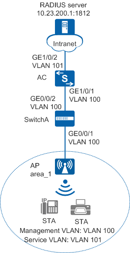
As shown in Figure 1, an AC in an enterprise is connected to the AP through access switch SwitchA. The enterprise deploys the WLAN wlan-net to provide wireless network access. The AC functions as a DHCP server to assign IP addresses on the network segment 10.23.101.0/24 to wireless users.
Because the WLAN is open to users, access control is required for the WLAN to ensure information security. Configure MAC address authentication to authenticate dumb terminals such as wireless network printers and wireless phones that do not support an authentication client. MAC addresses of terminals are used as user information and sent to the RADIUS server for authentication. When users connect to the WLAN, authentication is not required.
Data Planning
Item |
Data |
|---|---|
RADIUS authentication parameters |
Name of the RADIUS authentication scheme: radius_huawei Name of the RADIUS server template: radius_huawei
AAA domain: huawei.com |
MAC access profile |
|
Authentication profile |
|
DHCP server |
The AC functions as a DHCP server to assign IP addresses to the AP and STAs. |
IP address pool for the AP |
10.23.100.2 to 10.23.100.254/24 |
IP address pool for the STAs |
10.23.101.2 to 10.23.101.254/24 |
IP address of the AC's source interface |
VLANIF 100: 10.23.100.1/24 |
AP group |
|
Regulatory domain profile |
|
SSID profile |
|
Security profile |
|
VAP profile |
|
Configuration Roadmap
The configuration roadmap is as follows:
- Configure basic WLAN services so that the AC can communicate with upper-layer and lower-layer devices and the AP can go online.
- Configure RADIUS authentication parameters.
- Configure a MAC access profile to manage MAC access control parameters.
- Configure an authentication profile to manage NAC configuration.
- Configure WLAN service parameters, and bind a security policy profile and an authentication profile to a VAP profile to control access from STAs.
Procedure
- Set the NAC mode to unified mode on the AC (default setting). Configure SwitchA and the AC to allow the AP and AC to transmit CAPWAP packets.
# Add GE0/0/1 that connects SwitchA to the AP and GE0/0/2 that connects SwitchA to the AC to the management VLAN 100.
<HUAWEI> system-view
[HUAWEI] sysname SwitchA
[SwitchA] vlan batch 100
[SwitchA] interface gigabitethernet 0/0/1
[SwitchA-GigabitEthernet0/0/1] port link-type trunk
[SwitchA-GigabitEthernet0/0/1] port trunk pvid vlan 100
[SwitchA-GigabitEthernet0/0/1] port trunk allow-pass vlan 100
[SwitchA-GigabitEthernet0/0/1] undo port trunk allow-pass vlan 1
[SwitchA-GigabitEthernet0/0/1] stp edged-port enable
[SwitchA-GigabitEthernet0/0/1] port-isolate enable
[SwitchA-GigabitEthernet0/0/1] quit
[SwitchA] interface gigabitethernet 0/0/2
[SwitchA-GigabitEthernet0/0/2] port link-type trunk
[SwitchA-GigabitEthernet0/0/2] port trunk allow-pass vlan 100
[SwitchA-GigabitEthernet0/0/2] undo port trunk allow-pass vlan 1
[SwitchA-GigabitEthernet0/0/2] quit
# Add GE1/0/1 that connects the AC to SwitchA to VLAN 100.
<HUAWEI> system-view
[HUAWEI] sysname AC
[AC] vlan batch 100 101
[AC] interface gigabitethernet 1/0/1
[AC-GigabitEthernet1/0/1] port link-type trunk
[AC-GigabitEthernet1/0/1] port trunk allow-pass vlan 100
[AC-GigabitEthernet1/0/1] undo port trunk allow-pass vlan 1
[AC-GigabitEthernet1/0/1] quit
- Configure the AC to communicate with the upstream device.

Configure AC uplink interfaces to transparently transmit service VLAN packets as required and communicate with the upstream device.
# Add AC uplink interface GE1/0/2 to service VLAN 101.
[AC] interface gigabitethernet 1/0/2
[AC-GigabitEthernet1/0/2] port link-type trunk
[AC-GigabitEthernet1/0/2] port trunk allow-pass vlan 101
[AC-GigabitEthernet1/0/2] undo port trunk allow-pass vlan 1
[AC-GigabitEthernet1/0/2] quit
- Configure the AC as a DHCP server to allocate IP addresses to STAs and the AP.
# Configure the AC as the DHCP server to allocate an IP address to the AP from the IP address pool on VLANIF 100, and allocate IP addresses to STAs from the IP address pool on VLANIF 101.
Configure the DNS server as required. The common methods are as follows:- In interface address pool scenarios, run the dhcp server dns-list ip-address &<1-8> command in the VLANIF interface view.
- In global address pool scenarios, run the dns-list ip-address &<1-8> command in the IP address pool view.
[AC] dhcp enable  //Enable the DHCP function.
[AC] interface vlanif 100
[AC-Vlanif100] ip address 10.23.100.1 24
[AC-Vlanif100] dhcp select interface  //Configure an interface-based address pool.
[AC-Vlanif100] quit
[AC] interface vlanif 101
[AC-Vlanif101] ip address 10.23.101.1 24
[AC-Vlanif101] dhcp select interface
[AC-Vlanif101] quit
- Configure a route from the AC to the RADIUS server. (Assume that the IP address of the upper-layer device connected to the AC is 10.23.101.2.)
[AC] ip route-static 10.23.200.1 255.255.255.0 10.23.101.2
- Configure the AP to go online.
# Create an AP group.
[AC] wlan
[AC-wlan-view] ap-group name ap-group1
[AC-wlan-ap-group-ap-group1] quit
# Create a regulatory domain profile, configure the AC country code in the profile, and apply the profile to the AP group.
[AC-wlan-view] regulatory-domain-profile name domain1
[AC-wlan-regulate-domain-domain1] country-code cn
[AC-wlan-regulate-domain-domain1] quit
[AC-wlan-view] ap-group name ap-group1
[AC-wlan-ap-group-ap-group1] regulatory-domain-profile domain1
Warning: Modifying the country code will clear channel, power and antenna gain configurations of the radio and reset the AP. Continue?[Y/N]:y
[AC-wlan-ap-group-ap-group1] quit
[AC-wlan-view] quit
# Configure the AC's source interface.
[AC] capwap source interface vlanif 100
# Import an AP offline on the WLAN AC and add the AP to AP group ap-group1. Assume that the AP's MAC address is 60de-4476-e360. Configure a name for the AP based on the AP's deployment location, so that you can know where the AP is deployed from its name. For example, name the AP area_1 if it is deployed in Area 1. The default AP authentication mode is MAC address authentication. If the default settings are retained, you do not need to run the ap auth-mode mac-auth command.
The AP used in this example has two radios: radio 0 (2.4 GHz radio) and radio 1 (5 GHz radio).
[AC] wlan
[AC-wlan-view] ap auth-mode mac-auth
[AC-wlan-view] ap-id 0 ap-mac 60de-4476-e360
[AC-wlan-ap-0] ap-name area_1
[AC-wlan-ap-0] ap-group ap-group1
Warning: This operation may cause AP reset. If the country code changes, it will clear channel, power and antenna gain configuration s of the radio, Whether to continue? [Y/N]:y
[AC-wlan-ap-0] quit
# Power on the AP and run the display ap all command to check the AP state. If the State field is displayed as nor, the AP has gone online.
[AC-wlan-view] display ap all
Total AP information:
nor  : normal          [1]
Extrainfo : Extra information
P  : insufficient power supply
--------------------------------------------------------------------------------------------------
ID   MAC            Name   Group     IP            Type            State STA Uptime      ExtraInfo
--------------------------------------------------------------------------------------------------
0    60de-4476-e360 area_1 ap-group1 10.23.100.254 AP5030DN        nor   0   10S         -
--------------------------------------------------------------------------------------------------
Total: 1
- Configure a RADIUS server template and a RADIUS authentication scheme.
Ensure that the RADIUS server IP address, port number, and shared key are configured correctly and are the same as those on the RADIUS server.
# Configure a RADIUS server template.
[AC] radius-server template radius_huawei
[AC-radius-radius_huawei] radius-server authentication 10.23.200.1 1812
[AC-radius-radius_huawei] radius-server shared-key cipher Huawei@123
[AC-radius-radius_huawei] quit
# Configure a RADIUS authentication scheme.
[AC] aaa
[AC-aaa] authentication-scheme radius_huawei
[AC-aaa-authen-radius_huawei] authentication-mode radius
[AC-aaa-authen-radius_huawei] quit
# Create an AAA domain and configure the RADIUS server template and authentication scheme.
[AC-aaa] domain huawei.com
[AC-aaa-domain-huawei.com] radius-server radius_huawei
[AC-aaa-domain-huawei.com] authentication-scheme radius_huawei
[AC-aaa-domain-huawei.com] quit
[AC-aaa] quit
- Configure the MAC access profile m1.
In a MAC access profile, a MAC address without hyphens (-) is used as the user name and password for MAC address authentication.
[AC] mac-access-profile name m1
[AC-mac-access-profile-m1] quit
- Configure the authentication profile p1.
[AC] authentication-profile name p1
[AC-authen-profile-p1] mac-access-profile m1
[AC-authen-profile-p1] access-domain huawei.com mac-authen force
[AC-authen-profile-p1] quit
- Configure WLAN service parameters.
# Create security profile wlan-security and set the security policy in the profile. By default, the security policy is set to open system.
[AC] wlan
[AC-wlan-view] security-profile name wlan-security
[AC-wlan-sec-prof-wlan-security] quit
# Create SSID profile wlan-ssid and set the SSID name to wlan-net.
[AC-wlan-view] ssid-profile name wlan-ssid
[AC-wlan-ssid-prof-wlan-ssid] ssid wlan-net
[AC-wlan-ssid-prof-wlan-ssid] quit
# Create VAP profile wlan-vap, configure the data forwarding mode and service VLANs, and apply the security profile, SSID profile, and authentication profile to the VAP profile.
[AC-wlan-view] vap-profile name wlan-vap
[AC-wlan-vap-prof-wlan-vap] forward-mode tunnel
[AC-wlan-vap-prof-wlan-vap] service-vlan vlan-id 101
[AC-wlan-vap-prof-wlan-vap] security-profile wlan-security
[AC-wlan-vap-prof-wlan-vap] ssid-profile wlan-ssid
[AC-wlan-vap-prof-wlan-vap] authentication-profile p1
[AC-wlan-vap-prof-wlan-vap] quit
# Bind VAP profile wlan-vap to the AP group and apply the profile to radio 0 and radio 1 of the AP.
[AC-wlan-view] ap-group name ap-group1
[AC-wlan-ap-group-ap-group1] vap-profile wlan-vap wlan 1 radio 0
[AC-wlan-ap-group-ap-group1] vap-profile wlan-vap wlan 1 radio 1
[AC-wlan-ap-group-ap-group1] quit
- Commit the configuration.
[AC-wlan-view] commit all
Warning: Committing configuration may cause service interruption, continue?[Y/N]:y
- Verify the configuration.
After dumb terminals associate with the WLAN, authentication is performed automatically. Users can directly access the network after being authenticated.
Configuration Files
SwitchA configuration file
#
sysname SwitchA
#
vlan batch 100
#
interface GigabitEthernet0/0/1
 port link-type trunk
 port trunk pvid vlan 100
 undo port trunk allow-pass vlan 1
 port trunk allow-pass vlan 100
 stp edged-port enable
 port-isolate enable group 1
#
interface GigabitEthernet0/0/2
 port link-type trunk
 undo port trunk allow-pass vlan 1
 port trunk allow-pass vlan 100
#
return
AC configuration file
#
 sysname AC
#
vlan batch 100 to 101
#
authentication-profile name p1
 mac-access-profile m1
 access-domain huawei.com mac-authen force
#
dhcp enable
#
radius-server template radius_huawei
 radius-server shared-key cipher %^%#Oc6_BMCw#9gZ2@SMVtk!PAC6>Ou*eLW/"qLp+f#$%^%#
 radius-server authentication 10.23.200.1 1812 weight 80
#
mac-access-profile name m1
#
aaa
 authentication-scheme radius_huawei
  authentication-mode radius
 domain huawei.com
  authentication-scheme radius_huawei
  radius-server radius_huawei
#
interface Vlanif100
 ip address 10.23.100.1 255.255.255.0
 dhcp select interface
#
interface Vlanif101
 ip address 10.23.101.1 255.255.255.0
 dhcp select interface
#
interface GigabitEthernet1/0/1
 port link-type trunk
 undo port trunk allow-pass vlan 1
 port trunk allow-pass vlan 100
#
interface GigabitEthernet1/0/2
 port link-type trunk
 undo port trunk allow-pass vlan 1
 port trunk allow-pass vlan 101
#
ip route-static 10.23.200.0 255.255.255.0 10.23.101.2
#
capwap source interface vlanif100
#
wlan
 security-profile name wlan-security
 ssid-profile name wlan-ssid
  ssid wlan-net
 vap-profile name wlan-vap
  forward-mode tunnel
  service-vlan vlan-id 101
  ssid-profile wlan-ssid
  security-profile wlan-security
  authentication-profile p1
 regulatory-domain-profile name domain1
 ap-group name ap-group1
  regulatory-domain-profile domain1
  radio 0
   vap-profile wlan-vap wlan 1
  radio 1
   vap-profile wlan-vap wlan 1
 ap-id 0 ap-mac 60de-4476-e360
  ap-name area_1
  ap-group ap-group1
#
return