Example for Configuring Radio Calibration
Radio Calibration Overview
Radio calibration can dynamically adjust channels and power of APs managed by the same AC to ensure that the APs work optimally. On a WLAN, the operating status of APs is affected by the radio environment. For example, signal interference occurs if adjacent APs managed by the same AC work on overlapping channels or an AP has high power. In this case, you can configure radio calibration on the AC.
- During AP deployment, configure radio calibration to enable APs to automatically select the optimal channels.
- When new APs are added to a network or the network environment changes, configure radio calibration so that APs can adjust channels and power at scheduled time to work optimally.
Configuration Notes
In this example, the security policy is WPA2-PSK-CCMP. To ensure network security, choose an appropriate security policy according to your network configurations.
In tunnel forwarding mode, the management VLAN and service VLAN cannot be the same. If you set the forwarding mode to direct forwarding, you are not advised to configure the management VLAN and service VLAN to be the same.
In direct forwarding mode, configure port isolation on the interface directly connected to APs. If port isolation is not configured, many broadcast packets will be transmitted in the VLANs or WLAN users on different APs can directly communicate at Layer 2.
- Configure the management VLAN and service VLAN:
- In tunnel forwarding mode, service packets are encapsulated in a CAPWAP tunnel and forwarded to the AC. The AC then forwards the packets to the upper-layer network or APs. Service packets and management packets can be forwarded normally only if the network between the AC and APs is added to the management VLAN and the network between the AC and upper-layer network is added to the service VLAN.
- In direct forwarding mode, service packets are not encapsulated into a CAPWAP tunnel, but are directly forwarded to the upper-layer network or APs. Service packets and management packets can be forwarded normally only if the network between the AC and APs is added to the management VLAN and the network between APs and upper-layer network is added to the service VLAN.
- How to configure the source interface:
- In V200R006, run the wlan ac source interface { loopback loopback-number | vlanif vlan-id } command in the WLAN view.
- In V200R007 and V200R008, run the capwap source interface { loopback loopback-number | vlanif vlan-id } command in the system view.
- When configuring radio calibration, set the channel mode and power mode of an AP that needs radio calibration to auto.
- In the following example, scheduled radio calibration is used as an example. Configure the APs to perform radio calibration in off-peak hours, for example, between 00:00 am and 06:00 am.
- No ACK mechanism is provided for multicast packet transmission on air interfaces. In addition, wireless links are unstable. To ensure stable transmission of multicast packets, they are usually sent at low rates. If a large number of such multicast packets are sent from the network side, the air interfaces may be congested. You are advised to configure multicast packet suppression to reduce impact of a large number of low-rate multicast packets on the wireless network. Exercise caution when configuring the rate limit; otherwise, the multicast services may be affected.
- In direct forwarding mode, you are advised to configure multicast packet suppression on switch interfaces connected to APs.
- In tunnel forwarding mode, you are advised to configure multicast packet suppression in traffic profiles of the AC.
- The following table lists applicable products and versions.
Table 1 Applicable products and versions Software Version
Product Model
AP Model and Version
V200R005C00
S7700, S9700
V200R005C00:
AP2010DN, AP3010DN-AGN, AP5010DN-AGN, AP5010SN-GN, AP5030DN, AP5130DN, AP6010SN-GN, AP6010DN-AGN, AP6310SN-GN, AP6510DN-AGN, AP6610DN-AGN, AP7110DN-AGN, AP7110SN-GN
V200R006C00
S5720-HI, S7700, S9700
V200R005C00:
AP2010DN, AP3010DN-AGN, AP5010DN-AGN, AP5010SN-GN, AP5030DN, AP5130DN, AP6010SN-GN, AP6010DN-AGN, AP6310SN-GN, AP6510DN-AGN, AP6610DN-AGN, AP7110DN-AGN, AP7110SN-GN
V200R007C00
S5720-HI, S7700, S9700
V200R005C10:
AP2010DN, AP3010DN-AGN, AP5010DN-AGN, AP5010SN-GN, AP5030DN, AP5130DN, AP6010SN-GN, AP6010DN-AGN, AP6310SN-GN, AP6510DN-AGN, AP6610DN-AGN, AP7110DN-AGN, AP7110SN-GN, AP8030DN, AP8130DN
V200R005C20:
AP7030DE, AP9330DN
V200R008C00
S5720-HI, S7700, S9700
V200R005C10:
AP2010DN, AP3010DN-AGN, AP5010DN-AGN, AP5010SN-GN, AP5030DN, AP5130DN, AP6010SN-GN, AP6010DN-AGN, AP6310SN-GN, AP6510DN-AGN, AP6610DN-AGN, AP7110DN-AGN, AP7110SN-GN, AP8030DN, AP8130DN
V200R005C20:
AP7030DE, AP9330DN
V200R005C30:
AP2030DN, AP4030DN, AP4130DN

For S7700, you are advised to deploy S7712 or S7706 switches for WLAN services. S7703 switches are not recommended.
For S9700, you are advised to deploy S9712 or S9706 switches for WLAN services. S9703 switches are not recommended.
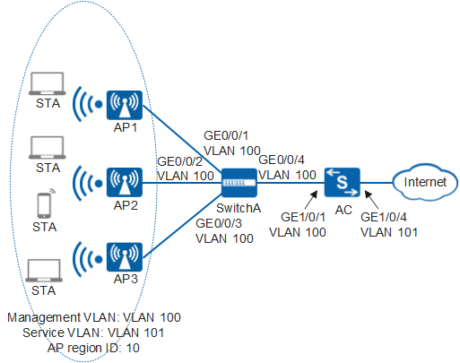
Networking Requirements
As shown in Figure 1, a WLAN containing three APs (AP1, AP2, and AP3) is deployed on the campus network. The three APs join AP region 10.
Users expect the three APs to automatically adjust their channels and power to reduce interference and perform optimally.
Data Planning
Item |
Data |
Description |
|---|---|---|
IP address of the AC's source interface |
192.168.10.1/24 |
None |
WMM profile |
Name: wmm |
None |
Radio profile |
Name: radio |
None |
Security profile |
|
None |
Traffic profile |
Name: traffic |
None |
Service set |
|
None |
DHCP server |
The AC functions as the DHCP server to assign IP addresses to APs and STAs. |
None |
AP gateway and IP address range |
VLANIF 100: 192.168.10.1/24 192.168.10.2 to 192.168.10.254/24 |
None |
STA gateway and IP address range |
VLANIF 101: 192.168.11.1/24 192.168.11.2 to 192.168.11.254/24 |
None |
MAC addresses of APs |
|
None |
Configuration Roadmap
- Configure basic WLAN services to ensure that users can access the Internet through WLAN.
- Set the radio calibration mode to schedule mode for APs to enable the APs to dynamically adjust channels and power so that the APs perform optimally.
Procedure
- Set the NAC mode to unified mode on the AC (default setting). Configure SwitchA and the AC to allow the APs and AC to transmit CAPWAP packets.
# Configure SwitchA and add interfaces GE0/0/1, GE0/0/2, GE0/0/3, and GE0/0/4 to VLAN 100 (management VLAN).
[HUAWEI] sysname SwitchA
[SwitchA] vlan batch 100
[SwitchA] interface gigabitethernet 0/0/1
[SwitchA-GigabitEthernet0/0/1] port link-type trunk
[SwitchA-GigabitEthernet0/0/1] port trunk pvid vlan 100
[SwitchA-GigabitEthernet0/0/1] port trunk allow-pass vlan 100
[SwitchA-GigabitEthernet0/0/1] quit
[SwitchA] interface gigabitethernet 0/0/2
[SwitchA-GigabitEthernet0/0/2] port link-type trunk
[SwitchA-GigabitEthernet0/0/2] port trunk pvid vlan 100
[SwitchA-GigabitEthernet0/0/2] port trunk allow-pass vlan 100
[SwitchA-GigabitEthernet0/0/2] quit
[SwitchA] interface gigabitethernet 0/0/3
[SwitchA-GigabitEthernet0/0/3] port link-type trunk
[SwitchA-GigabitEthernet0/0/3] port trunk pvid vlan 100
[SwitchA-GigabitEthernet0/0/3] port trunk allow-pass vlan 100
[SwitchA-GigabitEthernet0/0/3] quit
[SwitchA] interface gigabitethernet 0/0/4
[SwitchA-GigabitEthernet0/0/4] port link-type trunk
[SwitchA-GigabitEthernet0/0/4] port trunk allow-pass vlan 100
[SwitchA-GigabitEthernet0/0/4] quit
# Add GE1/0/1 that connects the AC to SwitchA to VLAN 100.
[HUAWEI] sysname AC
[AC] vlan batch 100
[AC] interface gigabitethernet 1/0/1
[AC-GigabitEthernet1/0/1] port link-type trunk
[AC-GigabitEthernet1/0/1] port trunk allow-pass vlan 100
[AC-GigabitEthernet1/0/1] quit
- Connect the AC to upstream devices.
# Add AC's uplink interface GE1/0/4 to VLAN 101.
[AC] vlan batch 101
[AC] interface gigabitethernet 1/0/4
[AC-GigabitEthernet1/0/4] port link-type trunk
[AC-GigabitEthernet1/0/4] port trunk allow-pass vlan 101
[AC-GigabitEthernet1/0/4] quit
- Configure the AC as a DHCP server to assign IP addresses to STAs and APs.
# Configure the AC as a DHCP server to assign IP addresses to the APs from the IP address pool on VLANIF 100 and assign IP addresses to STAs from the IP address pool on VLANIF 101.
[AC] dhcp enable //Enable the DHCP function.
[AC] interface vlanif 100
[AC-Vlanif100] ip address 192.168.10.1 24
[AC-Vlanif100] dhcp select interface  //Configure an interface-based address pool.
[AC-Vlanif100] quit
[AC] interface vlanif 101
[AC-Vlanif101] ip address 192.168.11.1 24
[AC-Vlanif101] dhcp select interface
[AC-Vlanif101] quit
- Configure AC system parameters.
# Configure the country code.
[AC] wlan ac-global country-code cn
Warning: Modify the country code may delete configuration on those AP which use
the global country code and reset them, continue?[Y/N]:y
# Configure the AC ID and carrier ID.
[AC] wlan ac-global ac id 1 carrier id other //The default AC ID is 0. Set the AC ID to 1.# Configure the source interface.
[AC] wlan
[AC-wlan-view] wlan ac source interface vlanif 100
- Manage APs on the AC.
# Check the MAC address of the AP and view the AP type ID.
[AC-wlan-view] display ap-type all
  All AP types information:
  ------------------------------------------------------------------------------
  ID     Type
  ------------------------------------------------------------------------------
  17     AP6010SN-GN
  19     AP6010DN-AGN
  21     AP6310SN-GN
  23     AP6510DN-AGN
  25     AP6610DN-AGN
  27     AP7110SN-GN
  28     AP7110DN-AGN
  29     AP5010SN-GN
  30     AP5010DN-AGN
  31     AP3010DN-AGN
  33     AP6510DN-AGN-US
  34     AP6610DN-AGN-US
  35     AP5030DN
  36     AP5130DN
  37     AP7030DE
  38     AP2010DN
  39     AP8130DN
  40     AP8030DN
  42     AP9330DN
  43     AP4030DN
  44     AP4130DN
  45     AP3030DN
  46     AP2030DN
  ------------------------------------------------------------------------------
  Total number: 23
# Set the AP authentication mode to MAC address authentication (default setting). Add the AP offline according to the AP type ID. Assume that the AP type is AP6010DN-AGN and the MAC addresses of the APs are 60de-4476-e360, dcd2-fc04-b500, and dcd2-fc96-e4c0 respectively.
[AC-wlan-view] ap id 1 type-id 19 mac 60de-4476-e360
[AC-wlan-ap-1] quit
[AC-wlan-view] ap id 2 type-id 19 mac dcd2-fc04-b500
[AC-wlan-ap-2] quit
[AC-wlan-view] ap id 3 type-id 19 mac dcd2-fc96-e4c0
[AC-wlan-ap-3] quit
# Configure an AP region and add the APs to the AP region.
[AC-wlan-view] ap-region id 10  //Create AP region 10.
[AC-wlan-ap-region-10] quit
[AC-wlan-view] ap id 1
[AC-wlan-ap-1] region-id 10  //Add APs to region 10.
[AC-wlan-ap-1] quit
[AC-wlan-view] ap id 2
[AC-wlan-ap-2] region-id 10
[AC-wlan-ap-2] quit
[AC-wlan-view] ap id 3
[AC-wlan-ap-3] region-id 10
[AC-wlan-ap-3] quit
# Power on the three APs and run the display ap all command on the AC to check the AP state. The command output shows that the APs are in normal state.
[AC-wlan-view] display ap all
  All AP information:
  Normal[3],Fault[0],Commit-failed[0],Committing[0],Config[0],Download[0]
  Config-failed[0],Standby[0],Type-not-match[0],Ver-mismatch[0]
  ------------------------------------------------------------------------------
  AP    AP                    AP              Profile   AP              AP
                                              /Region
  ID    Type                  MAC             ID        State           Sysname
  ------------------------------------------------------------------------------
  1     AP6010DN-AGN          60de-4476-e360    0/10    normal           ap-1
  2     AP6010DN-AGN          dcd2-fc04-b500    0/10    normal           ap-2
  3     AP6010DN-AGN          dcd2-fc96-e4c0    0/10    normal           ap-3
  ------------------------------------------------------------------------------
  Total number: 3,printed: 3
- Configure WLAN service parameters.
# Create a WMM profile named wmm and retain the default settings in the profile.
[AC-wlan-view] wmm-profile name wmm id 1
[AC-wlan-wmm-prof-wmm] quit
# Create a radio profile named radio and bind the WMM profile wmm to the radio profile. Set the channel mode and power mode to auto in the radio profile (default settings).
[AC-wlan-view] radio-profile name radio id 1
[AC-wlan-radio-prof-radio] wmm-profile name wmm
[AC-wlan-radio-prof-radio] quit
[AC-wlan-view] quit
# Create WLAN-ESS interface 1.
[AC] interface wlan-ess 1
[AC-Wlan-Ess1] port trunk allow-pass vlan 101
[AC-Wlan-Ess1] quit
# Create a security profile named security.
[AC] wlan
[AC-wlan-view] security-profile name security id 1
[AC-wlan-sec-prof-security] security-policy wpa2  //Configure security policy WPA2.
[AC-wlan-sec-prof-security] wpa2 authentication-method psk pass-phrase cipher huawei123 encryption-method ccmp //Set the encryption method to PSK+CCMP.
[AC-wlan-sec-prof-security] quit
# Create a traffic profile named traffic and retain the default settings in the profile.
[AC-wlan-view] traffic-profile name traffic id 1
[AC-wlan-traffic-prof-traffic] quit
# Create a service set named test and bind the WLAN-ESS interface, security profile, and traffic profile to the service set.
[AC-wlan-view] service-set name test id 1
[AC-wlan-service-set-test] ssid test  //Set the SSID name to test.
[AC-wlan-service-set-test] wlan-ess 1
[AC-wlan-service-set-test] security-profile name security
[AC-wlan-service-set-test] traffic-profile name traffic
[AC-wlan-service-set-test] service-vlan 101  //Set the VLAN ID for a service set to 101. The default VLAN ID for a service set is 1.
[AC-wlan-service-set-test] forward-mode tunnel  //Set the service forwarding mode to tunnel.
[AC-wlan-service-set-test] quit
- Configure VAPs and deliver VAP parameters to APs.
# Configure VAPs.
[AC-wlan-view] ap 1 radio 0
[AC-wlan-radio-1/0] radio-profile name radio  //Bind the radio profile to the radio.
[AC-wlan-radio-1/0] service-set name test  //Bind the service set to the radio.
[AC-wlan-radio-1/0] quit
[AC-wlan-view] ap 2 radio 0
[AC-wlan-radio-2/0] radio-profile name radio
[AC-wlan-radio-2/0] service-set name test
[AC-wlan-radio-2/0] quit
[AC-wlan-view] ap 3 radio 0
[AC-wlan-radio-3/0] radio-profile name radio
[AC-wlan-radio-3/0] service-set name test
[AC-wlan-radio-3/0] quit
- Configure radio calibration.
# Set the radio working mode to hybrid.
[AC-wlan-view] ap 1 radio 0
[AC-wlan-radio-1/0] work-mode hybrid
Warning: Modify the work mode may cause business interruption, continue?(y/n)[n]:y
[AC-wlan-radio-1/0] quit
[AC-wlan-view] ap 2 radio 0
[AC-wlan-radio-2/0] work-mode hybrid
Warning: Modify the work mode may cause business interruption, continue?(y/n)[n]:y
[AC-wlan-radio-2/0] quit
[AC-wlan-view] ap 3 radio 0
[AC-wlan-radio-3/0] work-mode hybrid
Warning: Modify the work mode may cause business interruption, continue?(y/n)[n]:y
[AC-wlan-radio-3/0] quit
# Set the radio calibration mode to schedule and configure the device to start radio calibration at 3:00 a.m. every day.
[AC-wlan-view] calibrate enable schedule time 03:00:00
# Enable radio calibration in the radio profile view (default setting).
# Commit the configuration.
[AC-wlan-view] commit ap 1
Warning: Committing configuration may cause service interruption, continue?[Y/N]y
[AC-wlan-view] commit ap 2
Warning: Committing configuration may cause service interruption, continue?[Y/N]y
[AC-wlan-view] commit ap 3
Warning: Committing configuration may cause service interruption, continue?[Y/N]y
- Verify the configuration.
- After the preceding configurations are complete, the AC begins to adjust the channels and power of the three APs to ensure that the APs perform optimally.
- STAs can connect to the WLAN with SSID test. Use AP1 as an example. Run the display station assoc-info ap 1 command on AC. The command output shows that the STAs associate with the WLAN test.
[AC-wlan-view] display station assoc-info ap 1
  ------------------------------------------------------------------------------
  STA MAC          AP ID   RADIO ID  SS ID    SSID
  ------------------------------------------------------------------------------
  14cf-9208-9abf   1       0         1        test
  ------------------------------------------------------------------------------
  Total stations: 1
You can run the display statistics calibrate ap 1 radio 0 command on AC to check radio calibration statistics on AP1.
[AC-wlan-view] display statistics calibrate ap 1 radio 0
  -----------------------------------------------------------------------
   Signal environment deterioration :1
   Power calibration                :1
   Channel calibration              :0
  -----------------------------------------------------------------------
Configuration Files
SwitchA configuration file
#
sysname SwitchA
#
vlan batch 100
#
interface gigabitethernet0/0/1
 port link-type trunk
 port trunk pvid vlan 100
 port trunk allow-pass vlan 100
#
interface gigabitethernet0/0/2
 port link-type trunk
 port trunk pvid vlan 100
 port trunk allow-pass vlan 100
#
interface gigabitethernet0/0/3
 port link-type trunk
 port trunk pvid vlan 100
 port trunk allow-pass vlan 100
#
interface gigabitethernet0/0/4
 port link-type trunk
 port trunk allow-pass vlan 100
#
return
AC configuration file
#
sysname AC
#
vlan batch 100 to 101
#
wlan ac-global carrier id other ac id 1
#
dhcp enable
#
interface Vlanif100
 ip address 192.168.10.1 255.255.255.0
 dhcp select interface
#
interface Vlanif101
 ip address 192.168.11.1 255.255.255.0
 dhcp select interface
#
interface gigabitethernet1/0/1
 port link-type trunk
 port trunk allow-pass vlan 100
#
interface gigabitethernet1/0/4
 port link-type trunk
 port trunk allow-pass vlan 101
#
interface Wlan-Ess1
 port trunk allow-pass vlan 101
#
wlan
 wlan ac source interface vlanif100
 ap-region id 10
 ap id 1 type-id 19 mac 60de-4476-e360 sn 210235419610CB002287
  region-id 10
 ap id 2 type-id 19 mac dcd2-fc04-b500 sn 210235555310CC000094
  region-id 10
 ap id 3 type-id 19 mac dcd2-fc96-e4c0 sn 210235582910D1000039
  region-id 10
 wmm-profile name wmm id 1
 traffic-profile name traffic id 1
 security-profile name security id 1
 service-set name test id 1
  forward-mode tunnel
  wlan-ess 1
  ssid test
  traffic-profile id 1
  security-profile id 1
  service-vlan 101
 calibrate enable schedule time 03:00:00
 radio-profile name radio id 1
  wmm-profile id 1
 ap 1 radio 0
  radio-profile id 1
  work-mode hybrid
  service-set id 1 wlan 1
 ap 2 radio 0
  radio-profile id 1
  work-mode hybrid
  service-set id 1 wlan 1
 ap 3 radio 0
  radio-profile id 1
  work-mode hybrid
  service-set id 1 wlan 1
#
return