Example for Configuring Traffic-based Dynamic Load Balancing
Traffic-based Dynamic Load Balancing Overview
Load balancing can evenly distribute AP traffic loads to ensure sufficient bandwidth for each STA. When a STA joins the network, the AC adds the APs that report the STA to a load balancing group, and then uses a load balancing algorithm to determine whether to allow access from the STA.
Dynamic load balancing applies to high-density wireless environments, such as stadiums and stations.
Static load balancing supports a limited number of group members, and all members must be manually added to the group and work on the same frequency band. Dynamic load balancing overcomes these limitations and better ensures bandwidth for each STA.
Configuration Notes
In this example, the security policy is WPA2-PSK-CCMP. To ensure network security, choose an appropriate security policy according to your network configurations.
In tunnel forwarding mode, the management VLAN and service VLAN cannot be the same. If you set the forwarding mode to direct forwarding, you are not advised to configure the management VLAN and service VLAN to be the same.
In direct forwarding mode, configure port isolation on the interface directly connected to APs. If port isolation is not configured, many broadcast packets will be transmitted in the VLANs or WLAN users on different APs can directly communicate at Layer 2.
- Configure the management VLAN and service VLAN:
- In tunnel forwarding mode, service packets are encapsulated in a CAPWAP tunnel and forwarded to the AC. The AC then forwards the packets to the upper-layer network or APs. Service packets and management packets can be forwarded normally only if the network between the AC and APs is added to the management VLAN and the network between the AC and upper-layer network is added to the service VLAN.
- In direct forwarding mode, service packets are not encapsulated into a CAPWAP tunnel, but are directly forwarded to the upper-layer network or APs. Service packets and management packets can be forwarded normally only if the network between the AC and APs is added to the management VLAN and the network between APs and upper-layer network is added to the service VLAN.
- How to configure the source interface:
- In V200R006, run the wlan ac source interface { loopback loopback-number | vlanif vlan-id } command in the WLAN view.
- In V200R007 and V200R008, run the capwap source interface { loopback loopback-number | vlanif vlan-id } command in the system view.
- Radio traffic statistics packets are sent and received together with Echo packets. In this example, traffic-based dynamic load balancing is used. You are advised to set the CAPWAP heartbeat detection interval to between 30s and 60s so that the radio traffic statistics can be updated in a timely manner.
- No ACK mechanism is provided for multicast packet transmission on air interfaces. In addition, wireless links are unstable. To ensure stable transmission of multicast packets, they are usually sent at low rates. If a large number of such multicast packets are sent from the network side, the air interfaces may be congested. You are advised to configure multicast packet suppression to reduce impact of a large number of low-rate multicast packets on the wireless network. Exercise caution when configuring the rate limit; otherwise, the multicast services may be affected.
- In direct forwarding mode, you are advised to configure multicast packet suppression on switch interfaces connected to APs.
- In tunnel forwarding mode, you are advised to configure multicast packet suppression in traffic profiles of the AC.
- The following table lists applicable products and versions.
Table 1 Applicable products and versions Software Version
Product Model
AP Model and Version
V200R005C00
S7700, S9700
V200R005C00:
AP2010DN, AP3010DN-AGN, AP5010DN-AGN, AP5010SN-GN, AP5030DN, AP5130DN, AP6010SN-GN, AP6010DN-AGN, AP6310SN-GN, AP6510DN-AGN, AP6610DN-AGN, AP7110DN-AGN, AP7110SN-GN
V200R006C00
S5720-HI, S7700, S9700
V200R005C00:
AP2010DN, AP3010DN-AGN, AP5010DN-AGN, AP5010SN-GN, AP5030DN, AP5130DN, AP6010SN-GN, AP6010DN-AGN, AP6310SN-GN, AP6510DN-AGN, AP6610DN-AGN, AP7110DN-AGN, AP7110SN-GN
V200R007C00
S5720-HI, S7700, S9700
V200R005C10:
AP2010DN, AP3010DN-AGN, AP5010DN-AGN, AP5010SN-GN, AP5030DN, AP5130DN, AP6010SN-GN, AP6010DN-AGN, AP6310SN-GN, AP6510DN-AGN, AP6610DN-AGN, AP7110DN-AGN, AP7110SN-GN, AP8030DN, AP8130DN
V200R005C20:
AP7030DE, AP9330DN
V200R008C00
S5720-HI, S7700, S9700
V200R005C10:
AP2010DN, AP3010DN-AGN, AP5010DN-AGN, AP5010SN-GN, AP5030DN, AP5130DN, AP6010SN-GN, AP6010DN-AGN, AP6310SN-GN, AP6510DN-AGN, AP6610DN-AGN, AP7110DN-AGN, AP7110SN-GN, AP8030DN, AP8130DN
V200R005C20:
AP7030DE, AP9330DN
V200R005C30:
AP2030DN, AP4030DN, AP4130DN

For S7700, you are advised to deploy S7712 or S7706 switches for WLAN services. S7703 switches are not recommended.
For S9700, you are advised to deploy S9712 or S9706 switches for WLAN services. S9703 switches are not recommended.
Networking Requirements
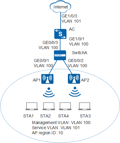
As shown in Figure 1, AP1 and AP2 connecting to the AC through SwitchA are dual-band APs and join AP region 10. STAs in AP region 10 support 2.4 GHz and 5 GHz frequency bands. Both 2.4 GHz and 5 GHz WLANs need to be deployed in AP region 10.
When a large number of STAs access the Internet through the same AP, the AP becomes heavily loaded and WLAN service quality deteriorates. Therefore, the STAs need to be balanced on the two APs.
Data Planning
Item |
Data |
Description |
|---|---|---|
IP address of the AC's source interface |
192.168.10.1/24 |
None |
WMM profile |
Name: wmm |
None |
Radio profile |
Name: radio |
None |
Security profile |
|
None |
Traffic profile |
Name: traffic |
None |
Service set |
|
None |
DHCP server |
The AC functions as the DHCP server to assign IP addresses to APs and STAs. |
None |
AP gateway and IP address range |
VLANIF 100: 192.168.10.1/24 192.168.10.2 to 192.168.10.254/24 |
None |
STA gateway and IP address range |
VLANIF 101: 192.168.11.1/24 192.168.11.2 to 192.168.11.254/24 |
None |
MAC addresses of APs |
|
None |
Configuration Roadmap
- Configure the WLAN service so that users can connect to the Internet through the WLAN.
- Configure traffic-based dynamic load balancing to prevent new STAs from associating with heavily-loaded APs.
Procedure
- Set the NAC mode to unified mode on the AC (default setting). Configure SwitchA and the AC to allow the APs and AC to transmit CAPWAP packets.
# Configure SwitchA and add interfaces GE0/0/1, GE0/0/2, and GE0/0/3 to the management VLAN 100.
[HUAWEI] sysname SwitchA
[SwitchA] vlan batch 100
[SwitchA] interface gigabitethernet 0/0/1
[SwitchA-GigabitEthernet0/0/1] port link-type trunk
[SwitchA-GigabitEthernet0/0/1] port trunk pvid vlan 100
[SwitchA-GigabitEthernet0/0/1] port trunk allow-pass vlan 100
[SwitchA-GigabitEthernet0/0/1] quit
[SwitchA] interface gigabitethernet 0/0/2
[SwitchA-GigabitEthernet0/0/2] port link-type trunk
[SwitchA-GigabitEthernet0/0/2] port trunk pvid vlan 100
[SwitchA-GigabitEthernet0/0/2] port trunk allow-pass vlan 100
[SwitchA-GigabitEthernet0/0/2] quit
[SwitchA] interface gigabitethernet 0/0/3
[SwitchA-GigabitEthernet0/0/3] port link-type trunk
[SwitchA-GigabitEthernet0/0/3] port trunk allow-pass vlan 100
[SwitchA-GigabitEthernet0/0/3] quit
# Add GE1/0/1 that connects the AC to SwitchA to VLAN 100.
[HUAWEI] sysname AC
[AC] vlan batch 100
[AC] interface gigabitethernet 1/0/1
[AC-GigabitEthernet1/0/1] port link-type trunk
[AC-GigabitEthernet1/0/1] port trunk allow-pass vlan 100
[AC-GigabitEthernet1/0/1] quit
- Configure the AC to communicate with the upstream device.
# Add the AC's uplink interface GE1/0/3 to VLAN 101.
[AC] vlan batch 101
[AC] interface gigabitethernet 1/0/3
[AC-GigabitEthernet1/0/3] port link-type trunk
[AC-GigabitEthernet1/0/3] port trunk allow-pass vlan 101
[AC-GigabitEthernet1/0/3] quit
- Configure the AC as a DHCP server to assign IP addresses to STAs and APs.
# Configure a DHCP server to assign IP addresses to the APs from the IP address pool on VLANIF 100 and assign IP addresses to STAs from the IP address pool on VLANIF 101.
[AC] dhcp enable  //Enable the DHCP function.
[AC] interface vlanif 100
[AC-Vlanif100] ip address 192.168.10.1 24
[AC-Vlanif100] dhcp select interface  //Configure an interface-based address pool.
[AC-Vlanif100] quit
[AC] interface vlanif 101
[AC-Vlanif101] ip address 192.168.11.1 24
[AC-Vlanif101] dhcp select interface
[AC-Vlanif101] quit
- Configure AC system parameters.
# Configure the country code.
[AC] wlan ac-global country-code cn
Warning: Modify the country code may delete configuration on those AP which use
the global country code and reset them, continue?[Y/N]:y
# Configure the AC ID and carrier ID.
[AC] wlan ac-global ac id 1 carrier id other //The default AC ID is 0. Set the AC ID to 1.# Configure the source interface.
[AC] wlan
[AC-wlan-view] wlan ac source interface vlanif 100
- Manage APs on the AC.
# Check the AP type IDs after obtaining the MAC addresses of the APs.
[AC-wlan-view] display ap-type all
  All AP types information:
  ------------------------------------------------------------------------------
  ID     Type
  ------------------------------------------------------------------------------
  17     AP6010SN-GN
  19     AP6010DN-AGN
  21     AP6310SN-GN
  23     AP6510DN-AGN
  25     AP6610DN-AGN
  27     AP7110SN-GN
  28     AP7110DN-AGN
  29     AP5010SN-GN
  30     AP5010DN-AGN
  31     AP3010DN-AGN
  33     AP6510DN-AGN-US
  34     AP6610DN-AGN-US
  35     AP5030DN
  36     AP5130DN
  37     AP7030DE
  38     AP2010DN
  39     AP8130DN
  40     AP8030DN
  42     AP9330DN
  43     AP4030DN
  44     AP4130DN
  45     AP3030DN
  46     AP2030DN
  ------------------------------------------------------------------------------
  Total number: 23
# Set the AP authentication mode to MAC address authentication (default setting). Add the APs offline based on the AP type ID. Assume that the type of AP1 and AP2 is AP6010DN-AGN, and their MAC addresses are 60de-4476-e360 and dcd2-fc04-b500, respectively.
[AC-wlan-view] ap-auth-mode mac-auth
[AC-wlan-view] ap id 1 type-id 19 mac 60de-4476-e360
[AC-wlan-ap-1] quit
[AC-wlan-view] ap id 2 type-id 19 mac dcd2-fc04-b500
[AC-wlan-ap-2] quit
# Configure an AP region and add the APs to the AP region.
[AC-wlan-view] ap-region id 10  //Create AP region 10.
[AC-wlan-ap-region-10] quit
[AC-wlan-view] ap id 1
[AC-wlan-ap-1] region-id 10  //Add APs to region 10.
[AC-wlan-ap-1] quit
[AC-wlan-view] ap id 2
[AC-wlan-ap-2] region-id 10
[AC-wlan-ap-2] quit
# Power on AP1 and AP2 and run the display ap all command on the AC to check the AP state. The command output shows that the APs are in normal state.
[AC-wlan-view] display ap all
  All AP information:
  Normal[2],Fault[0],Commit-failed[0],Committing[0],Config[0],Download[0]
  Config-failed[0],Standby[0],Type-not-match[0],Ver-mismatch[0]
  ------------------------------------------------------------------------------
  AP    AP                    AP              Profile   AP              AP
                                              /Region
  ID    Type                  MAC             ID        State           Sysname
  ------------------------------------------------------------------------------
  1     AP6010DN-AGN          60de-4476-e360    0/10    normal           ap-1
  2     AP6010DN-AGN          dcd2-fc04-b500    0/10    normal           ap-2
  ------------------------------------------------------------------------------
  Total number: 2,printed: 2
- Configure WLAN service parameters.
# Create a WMM profile named wmm and retain the default settings in the profile.
[AC-wlan-view] wmm-profile name wmm id 1
[AC-wlan-wmm-prof-wmm] quit
# Create a radio profile named radio and bind the WMM profile wmm to the radio profile. Set the channel mode to fixed.
[AC-wlan-view] radio-profile name radio id 1
[AC-wlan-radio-prof-radio] channel-mode fixed  //Set the channel mode fixed. The default value is auto.
[AC-wlan-radio-prof-radio] wmm-profile name wmm
[AC-wlan-radio-prof-radio] quit
[AC-wlan-view] quit
# Create WLAN-ESS interface 1.
[AC] interface wlan-ess 1
[AC-Wlan-Ess1] port trunk allow-pass vlan 101
[AC-Wlan-Ess1] quit
# Create a security profile named security.
[AC] wlan
[AC-wlan-view] security-profile name security id 1
[AC-wlan-sec-prof-security] security-policy wpa2  //Configure security policy WPA2.
[AC-wlan-sec-prof-security] wpa2 authentication-method psk pass-phrase cipher huawei123 encryption-method ccmp  //Set the encryption method to PSK+CCMP.
[AC-wlan-sec-prof-security] quit
# Create a traffic profile named traffic and retain the default settings in the profile.
[AC-wlan-view] traffic-profile name traffic id 1
[AC-wlan-traffic-prof-traffic] quit
# Create a service set named test and bind the WLAN-ESS interface, security profile, and traffic profile to the service set.
[AC-wlan-view] service-set name test id 1
[AC-wlan-service-set-test] ssid test  //Name the SSID test.
[AC-wlan-service-set-test] wlan-ess 1
[AC-wlan-service-set-test] security-profile name security
[AC-wlan-service-set-test] traffic-profile name traffic
[AC-wlan-service-set-test] service-vlan 101  //Set the VLAN ID of the service set to 101. The default value is 1.
[AC-wlan-service-set-test] forward-mode tunnel  //Set the service forwarding mode to tunnel forwarding.
[AC-wlan-service-set-test] quit
- Configure VAPs and deliver VAP parameters to APs.
# Configure VAPs.
[AC-wlan-view] ap 1 radio 0
[AC-wlan-radio-1/0] radio-profile name radio  //Bind the radio profile to a radio.
[AC-wlan-radio-1/0] channel 20mhz 11  //Set the working channel of the radio to 11 and the channel bandwidth to 20 MHz.
[AC-wlan-radio-1/0] service-set name test  //Bind the service set to the radio.
[AC-wlan-radio-1/0] quit
[AC-wlan-view] ap 1 radio 1
[AC-wlan-radio-1/1] radio-profile name radio
[AC-wlan-radio-1/1] channel 40mhz-plus 157   //Set the working channel of the radio to 157 and the channel bandwidth to 40MHz Plus.
[AC-wlan-radio-1/1] service-set name test
[AC-wlan-radio-1/1] quit
[AC-wlan-view] ap 2 radio 0
[AC-wlan-radio-2/0] radio-profile name radio
[AC-wlan-radio-2/0] channel 20mhz 6
[AC-wlan-radio-2/0] service-set name test
[AC-wlan-radio-2/0] quit
[AC-wlan-view] ap 2 radio 1
[AC-wlan-radio-2/1] radio-profile name radio
[AC-wlan-radio-2/1] channel 40mhz-plus 149
[AC-wlan-radio-2/1] service-set name test
[AC-wlan-radio-2/1] quit
- Configure dynamic load balancing.
[AC-wlan-view] sta-load-balance enable  //Enable dynamic load balancing.
[AC-wlan-view] sta-load-balance mode traffic  //Configure traffic-based dynamic load balancing.
[AC-wlan-view] sta-load-balance traffic gap 25  //Set the load difference threshold to 25%. The default value is 20%.
[AC-wlan-view] sta-load-balance associate-threshold 10  //Set the maximum number of association requests in dynamic load balancing to 10. The default value is 6.
[AC-wlan-view] commit ap 1  //Commit the configuration.
Warning: Committing configuration may cause service interruption, continue?[Y/N]y
[AC-wlan-view] commit ap 2
Warning: Committing configuration may cause service interruption, continue?[Y/N]y
[AC-wlan-view] quit
- Verify the configuration.
- After the preceding configuration is complete, STAs can discover the WLAN with SSID test.
- You can run the display sta-load-balance config command on the AC to check the dynamic load balancing configuration.
[AC] display sta-load-balance config Sta-load-balance config: ------------------------------------------------------------------------------ Sta-load-balance enable : Yes Sta-load-balance mode : Traffic Sta-load-balance session gap threshold : 4 Sta-load-balance traffic gap threshold : 25 Sta-load-balance associate threshold : 10 ------------------------------------------------------------------------------ - If a new STA requests to connect to one of the four VAPs in AP region 10, the AC uses a dynamic load balancing algorithm to determine whether to allow access from the STA. If the requested VAP has more than 25% greater load than the other VAPs, the AC rejects the association request of the STA. If the STA continues to send more than 10 association requests to the VAP, the AC allows the STA to associate with the AP.
Configuration Files
SwitchA configuration file
#
sysname SwitchA
#
vlan batch 100
#
interface GigabitEthernet0/0/1
 port link-type trunk
 port trunk pvid vlan 100
 port trunk allow-pass vlan 100
#
interface GigabitEthernet0/0/2
 port link-type trunk
 port trunk pvid vlan 100
 port trunk allow-pass vlan 100
#
interface GigabitEthernet0/0/3
 port link-type trunk
 port trunk allow-pass vlan 100
#
return
AC configuration file
#
sysname AC
#
vlan batch 100 to 101
#
wlan ac-global carrier id other ac id 1
#
dhcp enable
#
interface Vlanif100
 ip address 192.168.10.1 255.255.255.0
 dhcp select interface
#
interface Vlanif101
 ip address 192.168.11.1 255.255.255.0
 dhcp select interface
#
interface GigabitEthernet1/0/1
 port link-type trunk
 port trunk allow-pass vlan 100
#
interface GigabitEthernet1/0/3
 port link-type trunk
 port trunk allow-pass vlan 101
#
interface Wlan-Ess1
 port trunk allow-pass vlan 101
#
wlan
 wlan ac source interface vlanif100
 ap-region id 10
 ap id 1 type-id 19 mac 60de-4476-e360 sn 210235419610CB002287
  region-id 10
 ap id 2 type-id 19 mac dcd2-fc04-b500 sn 210235555310CC000094
  region-id 10
 wmm-profile name wmm id 1
 traffic-profile name traffic id 1
 security-profile name security id 1
 sta-load-balance enable
 sta-load-balance mode traffic
 sta-load-balance traffic gap 25
 sta-load-balance associate-threshold 10
 service-set name test id 1
  forward-mode tunnel
  wlan-ess 1
  ssid test
  traffic-profile id 1
  security-profile id 1
  service-vlan 101
 radio-profile name radio id 1
  channel-mode fixed
  wmm-profile id 1
 ap 1 radio 0
  radio-profile id 1
  channel 20MHz 11
  service-set id 1 wlan 1
 ap 1 radio 1
  radio-profile id 1
  channel 40MHz-plus 157
  service-set id 1 wlan 1
 ap 2 radio 0
  radio-profile id 1
  channel 20MHz 6
  service-set id 1 wlan 1
 ap 2 radio 1
  radio-profile id 1
  channel 40MHz-plus 149
  service-set id 1 wlan 1
#
return