Example for Configuring Portal Authentication on the Wireless Side
Portal Authentication on the Wireless Side Overview
Portal authentication, also known as web authentication, uses a Portal website to authenticate users when they go online. The users can use network resources only after they pass the authentication.
A user can access a known Portal authentication website and enter a user name and password for authentication. This mode is called active authentication. If a user attempts to access other external networks through HTTP, the device forcibly redirects the user to the Portal authentication website. This mode is called forcible authentication.
Configuration Notes
In tunnel forwarding mode, the management VLAN and service VLAN cannot be the same. If you set the forwarding mode to direct forwarding, you are not advised to configure the management VLAN and service VLAN to be the same.
In direct forwarding mode, configure port isolation on the interface directly connected to APs. If port isolation is not configured, many broadcast packets will be transmitted in the VLANs or WLAN users on different APs can directly communicate at Layer 2.
- Configure the management VLAN and service VLAN:
- In tunnel forwarding mode, service packets are encapsulated in a CAPWAP tunnel and forwarded to the AC. The AC then forwards the packets to the upper-layer network or APs. Service packets and management packets can be forwarded normally only if the network between the AC and APs is added to the management VLAN and the network between the AC and upper-layer network is added to the service VLAN.
- In direct forwarding mode, service packets are not encapsulated into a CAPWAP tunnel, but are directly forwarded to the upper-layer network or APs. Service packets and management packets can be forwarded normally only if the network between the AC and APs is added to the management VLAN and the network between APs and upper-layer network is added to the service VLAN.
- How to configure the source interface:
- In V200R006, run the wlan ac source interface { loopback loopback-number | vlanif vlan-id } command in the WLAN view.
- In V200R007 and V200R008, run the capwap source interface { loopback loopback-number | vlanif vlan-id } command in the system view.
- The following table lists applicable products and versions.
Table 1 Applicable products and versions Software Version
Product Model
AP Model and Version
V200R005C00
S7700, S9700
V200R005C00:
AP2010DN, AP3010DN-AGN, AP5010DN-AGN, AP5010SN-GN, AP5030DN, AP5130DN, AP6010SN-GN, AP6010DN-AGN, AP6310SN-GN, AP6510DN-AGN, AP6610DN-AGN, AP7110DN-AGN, AP7110SN-GN
V200R006C00
S5720-HI, S7700, S9700
V200R005C00:
AP2010DN, AP3010DN-AGN, AP5010DN-AGN, AP5010SN-GN, AP5030DN, AP5130DN, AP6010SN-GN, AP6010DN-AGN, AP6310SN-GN, AP6510DN-AGN, AP6610DN-AGN, AP7110DN-AGN, AP7110SN-GN
V200R007C00
S5720-HI, S7700, S9700
V200R005C10:
AP2010DN, AP3010DN-AGN, AP5010DN-AGN, AP5010SN-GN, AP5030DN, AP5130DN, AP6010SN-GN, AP6010DN-AGN, AP6310SN-GN, AP6510DN-AGN, AP6610DN-AGN, AP7110DN-AGN, AP7110SN-GN, AP8030DN, AP8130DN
V200R005C20:
AP7030DE, AP9330DN
V200R008C00
S5720-HI, S7700, S9700
V200R005C10:
AP2010DN, AP3010DN-AGN, AP5010DN-AGN, AP5010SN-GN, AP5030DN, AP5130DN, AP6010SN-GN, AP6010DN-AGN, AP6310SN-GN, AP6510DN-AGN, AP6610DN-AGN, AP7110DN-AGN, AP7110SN-GN, AP8030DN, AP8130DN
V200R005C20:
AP7030DE, AP9330DN
V200R005C30:
AP2030DN, AP4030DN, AP4130DN

For S7700, you are advised to deploy S7712 or S7706 switches for WLAN services. S7703 switches are not recommended.
For S9700, you are advised to deploy S9712 or S9706 switches for WLAN services. S9703 switches are not recommended.
Networking Requirements
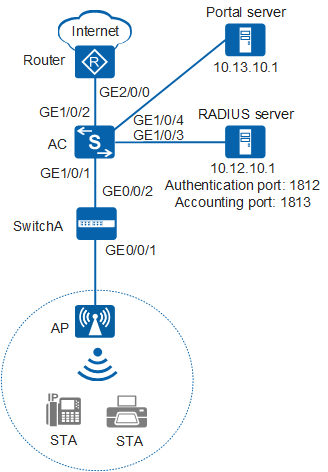
As shown in Figure 1, the AC deployed in a public area connects to the egress gateway (Router), RADIUS server, and Portal server, and connects to the AP through SwitchA. Users can access network resources through the WLAN with the SSID of test. The gateway also functions as a DHCP server to assign IP addresses on the 10.10.10.0/24 network segment to STAs, which are managed by the AC.
Because the WLAN is too easy for users to access, there are potential security risks. To facilitate access to the WLAN, use the default security policy on the AC, in which STAs are not authenticated and data is not encrypted. To centrally manage STAs and allow only paid users to access the Internet, configure Portal authentication on the AC. Any user who attempts to access the Internet is redirected to the Portal authentication web page. A paying user connects to the Internet after entering the user name and password, and the RADIUS server starts accounting. A non-paying user must pay for the WLAN service and use the obtained user name and password to complete Portal authentication. Generally, the Portal authentication web page provides the paying function.
Data planning
Configuration Item |
Data |
|---|---|
WLAN service |
Open system authentication+non-encryption |
Management VLAN |
VLAN 100 |
Service VLAN |
VLAN 101 |
Source interface on the AC |
VLANIF 100: 192.168.10.1/24 |
AC carrier ID/AC ID |
Other/1 |
AP region ID |
10 |
Service set |
|
SwitchA VLAN |
VLAN 100 |
DHCP server |
|
Gateway for the AP |
VLANIF 100: 192.168.10.1/24 |
Gateway for STAs |
VLANIF 101: 10.10.10.1/24 |
RADIUS server parameters |
|
User name and password of STAs |
|
Portal server parameters |
|
Configuration Roadmap
- Configure WLAN basic services so that STAs can access the WLAN. This example uses default configurations.
- Configure a RADIUS server template, apply it to an AAA domain, and use a RADIUS server to authenticate STAs' identities and perform accounting.
- Configure Portal authentication so that Hypertext Transfer Protocol (HTTP) request packets from a user are redirected to the web page of the Portal server. After the user enters identity information, the STA sends the user identity information to the RADIUS server.
Procedure
- Set the NAC mode to unified mode on the AC (default setting). Configure SwitchA and the AC to allow the AP and AC to transmit CAPWAP packets.
# Add GE0/0/1 that connects SwitchA to the AP and GE0/0/2 that connects SwitchA to the AC to the management VLAN 100.
<HUAWEI> system-view
[HUAWEI] sysname SwitchA
[SwitchA] vlan batch 100
[SwitchA] interface gigabitethernet 0/0/1
[SwitchA-GigabitEthernet0/0/1] port link-type trunk
[SwitchA-GigabitEthernet0/0/1] port trunk pvid vlan 100
[SwitchA-GigabitEthernet0/0/1] port trunk allow-pass vlan 100
[SwitchA-GigabitEthernet0/0/1] quit
[SwitchA] interface gigabitethernet 0/0/2
[SwitchA-GigabitEthernet0/0/2] port link-type trunk
[SwitchA-GigabitEthernet0/0/2] port trunk allow-pass vlan 100
[SwitchA-GigabitEthernet0/0/2] quit
# Add GE1/0/1 that connects the AC to SwitchA to VLAN 100.
<HUAWEI> system-view
[HUAWEI] sysname AC
[AC] vlan batch 100 101
[AC] interface gigabitethernet 1/0/1
[AC-GigabitEthernet1/0/1] port link-type trunk
[AC-GigabitEthernet1/0/1] port trunk allow-pass vlan 100
[AC-GigabitEthernet1/0/1] quit
- Configure the AC to communicate with the upstream device.
# Configure VLANIF 101 (service VLAN), VLANIF 102, VLANIF 103, and VLANIF 104.
[AC] vlan batch 101 102 103 104
[AC] interface vlanif 101
[AC-Vlanif101] ip address 10.10.10.1 24
[AC-Vlanif101] quit
[AC] interface vlanif 102
[AC-Vlanif102] ip address 10.11.10.2 24
[AC-Vlanif102] quit
[AC] interface vlanif 103
[AC-Vlanif103] ip address 10.12.10.2 24
[AC-Vlanif103] quit
[AC] interface vlanif 104
[AC-Vlanif104] ip address 10.13.10.2 24
[AC-Vlanif104] quit
# Add GE1/0/2 that connects the AC to the Router to VLAN 102.
[AC] interface gigabitethernet 1/0/2
[AC-GigabitEthernet1/0/2] port link-type trunk
[AC-GigabitEthernet1/0/2] port trunk allow-pass vlan 102
[AC-GigabitEthernet1/0/2] quit
# Add GE1/0/3 that connects the AC to the RADIUS server to VLAN 103.
[AC] interface gigabitethernet 1/0/3
[AC-GigabitEthernet1/0/3] port link-type trunk
[AC-GigabitEthernet1/0/3] port trunk allow-pass vlan 103
[AC-GigabitEthernet1/0/3] quit
# Add GE1/0/4 that connects the AC to the Portal server to VLAN 104.
[AC] interface gigabitethernet 1/0/4
[AC-GigabitEthernet1/0/4] port link-type trunk
[AC-GigabitEthernet1/0/4] port trunk allow-pass vlan 104
[AC-GigabitEthernet1/0/4] quit
# On the AC, configure a default route.
[AC] ip route-static 0.0.0.0 0.0.0.0 10.11.10.1
- Configure the AC to assign an IP address to the AP and configure the Router to assign IP addresses to STAs.
# Configure the AC to assign an IP address to the AP from an interface IP address pool.
[AC] dhcp enable
[AC] interface vlanif 100
[AC-Vlanif100] ip address 192.168.10.1 24
[AC-Vlanif100] dhcp select interface  //Configure an interface-based address pool.
[AC-Vlanif100] quit
# Configure the AC as the DHCP relay agent and enable user entry detection on the AC.
[AC] interface vlanif 101
[AC-Vlanif101] dhcp select relay  //Configure the DHCP relay function.
[AC-Vlanif101] dhcp relay server-ip 10.11.10.1  //Set the DHCP server address for DHCP relay to 10.11.10.1, which resides on Router.
[AC-Vlanif101] quit
# Configure the Router as a DHCP server to assign IP addresses to STAs.
<Huawei> system-view
[Huawei] sysname Router
[Router] dhcp enable
[Router] ip pool sta  //Configure the address pool to assign IP addresses to STAs.
[Router-ip-pool-sta] gateway-list 10.10.10.1
[Router-ip-pool-sta] network 10.10.10.0 mask 24
[Router-ip-pool-sta] quit
[Router] vlan batch 102
[Router] interface vlanif 102
[Router-Vlanif102] ip address 10.11.10.1 24
[Router-Vlanif102] dhcp select global  //Configure a global address pool.
[Router-Vlanif102] quit
[Router] interface gigabitethernet 2/0/0
[Router-GigabitEthernet2/0/0] port link-type trunk
[Router-GigabitEthernet2/0/0] port trunk allow-pass vlan 102
[Router-GigabitEthernet2/0/0] quit
[Router] ip route-static 10.10.10.0 24 10.11.10.2  //Configure a route on the Router destined for the network segment 10.10.10.0/24.
- Configure RADIUS authentication and accounting.
# Configure a RADIUS server template, an AAA authentication scheme, an AAA accounting scheme, and domain information.
[AC] radius-server template radius_huawei
[AC-radius-radius_huawei] radius-server authentication 10.12.10.1 1812
[AC-radius-radius_huawei] radius-server accounting 10.12.10.1 1813
[AC-radius-radius_huawei] radius-server shared-key cipher 123456    //The default key is huawei.
[AC-radius-radius_huawei] quit
[AC] aaa
[AC-aaa] authentication-scheme radius_huawei
[AC-aaa-authen-radius_huawei] authentication-mode radius
[AC-aaa-authen-radius_huawei] quit
[AC-aaa] accounting-scheme radius_huawei
[AC-aaa-accounting-radius_huawei] accounting-mode radius
[AC-aaa-accounting-radius_huawei] quit
[AC-aaa] domain huawei.com
[AC-aaa-domain-huawei.com] authentication-scheme radius_huawei
[AC-aaa-domain-huawei.com] accounting-scheme radius_huawei
[AC-aaa-domain-huawei.com] radius-server radius_huawei
[AC-aaa-domain-huawei.com] quit
[AC-aaa] quit
# Test whether a STA can be authenticated using RADIUS authentication.
[AC] test-aaa test@huawei.com 123456 radius-template radius_huawei
Info: Account test succeed.
- Configure Portal authentication.
# Configuring Portal server parameters. Set the port number to 50100 (default setting).
[AC] web-auth-server test
[AC-web-auth-server-test] server-ip 10.13.10.1
[AC-web-auth-server-test] shared-key cipher huawei
[AC-web-auth-server-test] url http://10.13.10.1
[AC-web-auth-server-test] quit
- Configure AC system parameters.
# Configure the country code.
[AC] wlan ac-global country-code cn
Warning: Modify the country code may delete configuration on those AP which use
the global country code and reset them, continue?[Y/N]:y
# Configure the AC ID and carrier ID.
[AC] wlan ac-global ac id 1 carrier id other //The default AC ID is 0. Set the AC ID to 1.# Configure the source interface.
[AC] wlan
[AC-wlan-view] wlan ac source interface vlanif 100
- Manage the AP on the AC.
# Check the AP type ID after obtaining the MAC address of the AP.
[AC-wlan-view] display ap-type all
  All AP types information:
  ------------------------------------------------------------------------------
  ID     Type
  ------------------------------------------------------------------------------
  17     AP6010SN-GN
  19     AP6010DN-AGN
  21     AP6310SN-GN
  23     AP6510DN-AGN
  25     AP6610DN-AGN
  27     AP7110SN-GN
  28     AP7110DN-AGN
  29     AP5010SN-GN
  30     AP5010DN-AGN
  31     AP3010DN-AGN
  33     AP6510DN-AGN-US
  34     AP6610DN-AGN-US
  35     AP5030DN
  36     AP5130DN
  37     AP7030DE
  38     AP2010DN
  39     AP8130DN
  40     AP8030DN
  42     AP9330DN
  43     AP4030DN
  44     AP4130DN
  45     AP3030DN
  46     AP2030DN
  ------------------------------------------------------------------------------
  Total number: 23
# Set the AP authentication mode to MAC address authentication (default setting). Add the AP offline based on the AP type ID. Assume that the AP type is AP6010DN-AGN, and the MAC address of the AP is 60de-4476-e360.
[AC-wlan-view] ap id 0 type-id 19 mac 60de-4476-e360
[AC-wlan-ap-0] quit
# Configure an AP region and add the AP to the AP region.
[AC-wlan-view] ap-region id 10  //Create AP region 10.
[AC-wlan-ap-region-10] quit
[AC-wlan-view] ap id 0
[AC-wlan-ap-0] region-id 10  //Add AP to region 10.
[AC-wlan-ap-0] quit
# Power on the APs and run the display ap all command on the AC to check the AP running status. The command output shows that the AP status is normal.
[AC-wlan-view] display ap all All AP information: Normal[1],Fault[0],Commit-failed[0],Committing[0],Config[0],Download[0] Config-failed[0],Standby[0],Type-not-match[0],Ver-mismatch[0] ------------------------------------------------------------------------------ AP AP AP Profile AP AP /Region ID Type MAC ID State Sysname ------------------------------------------------------------------------------ 0 AP6010DN-AGN 60de-4476-e360 0/10 normal ap-0 ------------------------------------------------------------------------------ Total number: 1,printed: 1 - Configure WLAN service parameters.
# Create a WMM profile named wmm.
[AC-wlan-view] wmm-profile name wmm id 1
[AC-wlan-wmm-prof-wmm] quit
# Create a radio profile named radio and bind the WMM profile wmm to the radio profile.
[AC-wlan-view] radio-profile name radio id 1
[AC-wlan-radio-prof-radio] wmm-profile name wmm
[AC-wlan-radio-prof-radio] quit
[AC-wlan-view] quit
# Create WLAN-ESS interface 1.
[AC] interface wlan-ess 1
[AC-Wlan-Ess1] port trunk allow-pass vlan 101
[AC-Wlan-Ess1] quit
# Create a security profile named security.
[AC] wlan
[AC-wlan-view] security-profile name security id 1
[AC-wlan-sec-prof-security] quit
# Create a traffic profile named traffic.
[AC-wlan-view] traffic-profile name traffic id 1
[AC-wlan-traffic-prof-traffic] quit
# Create a service set named test and bind the WLAN-ESS interface, security profile, and traffic profile to the service set.
[AC-wlan-view] service-set name test id 1
[AC-wlan-service-set-test] ssid test    //Set the SSID name to test.
[AC-wlan-service-set-test] wlan-ess 1
[AC-wlan-service-set-test] security-profile name security
[AC-wlan-service-set-test] traffic-profile name traffic
[AC-wlan-service-set-test] service-vlan 101    //Set the VLAN ID of the service set to 101. The default value is 1.
[AC-wlan-service-set-test] forward-mode tunnel    //Set the forwarding mode to tunnel forwarding.
[AC-wlan-service-set-test] quit
- Configure Portal authentication on the WLAN-ESS interface.
[AC-wlan-view] quit
[AC] interface wlan-ess 1
[AC-Wlan-Ess1] domain name huawei.com force
[AC-Wlan-Ess1] permit-domain name huawei.com
[AC-Wlan-Ess1] authentication portal
[AC-Wlan-Ess1] web-auth-server test direct
[AC-Wlan-Ess1] quit
[AC] wlan
- Configure a VAP and deliver VAP parameters to the AP.
# Configure a VAP.
[AC-wlan-view] ap 0 radio 0
[AC-wlan-radio-0/0] radio-profile name radio  //Bind the radio template to a radio.
[AC-wlan-radio-0/0] service-set name test  //Bind the service set to the radio.
[AC-wlan-radio-0/0] quit
# Commit the configuration.
[AC-wlan-view] commit ap 0 Warning: Committing configuration may cause service interruption, continue?[Y/N]y - Verify the configuration.
- The WLAN with SSID test is available for STAs connected to the AP.
- The wireless PC obtains an IP address after it associates with the WLAN.
- When a user opens their browser and attempts to access the network, the user is automatically redirected to the authentication page. After entering the correct user name and password on the page, the user can log in to the network.
Configuration Files
SwitchA configuration file
#
sysname SwitchA
#
vlan batch 100
#
interface GigabitEthernet0/0/1
 port link-type trunk
 port trunk pvid vlan 100
 port trunk allow-pass vlan 100
#
interface GigabitEthernet0/0/2
 port link-type trunk
 port trunk allow-pass vlan 100
#
return
Router configuration file
#
sysname Router
#
vlan batch 102
#
dhcp enable
#
ip pool sta
 gateway-list 10.10.10.1
 network 10.10.10.0 mask 255.255.255.0
#
interface Vlanif102
 ip address 10.11.10.1 255.255.255.0
 dhcp select global
#
interface GigabitEthernet2/0/0
 port link-type trunk
 port trunk allow-pass vlan 102
#
ip route-static 10.10.10.0 255.255.255.0 10.11.10.2
#
return
AC configuration file
#
 sysname AC
#
 vlan batch 100 to 104
#
wlan ac-global carrier id other ac id 1
#
dhcp enable
#
radius-server template radius_huawei
 radius-server authentication 10.12.10.1 1812 weight 80
 radius-server accounting 10.12.10.1 1813 weight 80
 radius-server shared-key cipher %#%#Dh.LR>nZA,K_(/~3#i!@a;6}Vk\T_9`ocp<^c"q%%#%
#
web-auth-server test
 server-ip 10.13.10.1
 port 50100
 shared-key cipher %#%#Q"r\<Ei]o@"%dKN@Y(i,:nj2IY$e>=mXxg8Cdb]0%#%#
 url http://10.13.10.1
#
aaa
 authentication-scheme radius_huawei
  authentication-mode radius
 accounting-scheme radius_huawei
  accounting-mode radius
 domain huawei.com
  authentication-scheme radius_huawei
  accounting-scheme radius_huawei
  radius-server radius_huawei
#
interface Vlanif100
 ip address 192.168.10.1 255.255.255.0
 dhcp select interface
#
interface Vlanif101
 ip address 10.10.10.1 255.255.255.0
 dhcp select relay
 dhcp relay server-ip 10.11.10.1
#
interface Vlanif102
 ip address 10.11.10.2 255.255.255.0
#
interface Vlanif103
 ip address 10.12.10.2 255.255.255.0
#
interface Vlanif104
 ip address 10.13.10.2 255.255.255.0
#
interface GigabitEthernet1/0/1
 port link-type trunk
 port trunk allow-pass vlan 100
#
interface GigabitEthernet1/0/2
 port link-type trunk
 port trunk allow-pass vlan 102
#
interface GigabitEthernet1/0/3
 port link-type trunk
 port trunk allow-pass vlan 103
#
interface GigabitEthernet1/0/4
 port link-type trunk
 port trunk allow-pass vlan 104
#
interface Wlan-Ess1
 port trunk allow-pass vlan 101
 permit-domain name huawei.com
 domain name huawei.com force
 web-auth-server test direct
 authentication portal
#
wlan
 wlan ac source interface vlanif100
 ap-region id 10
 ap id 0 type-id 19 mac 60de-4476-e360 sn AB35015384
  region-id 10
 wmm-profile name wmm id 1
 traffic-profile name traffic id 1
 security-profile name security id 1
 service-set name test id 1
  forward-mode tunnel
  wlan-ess 1
  ssid test
  traffic-profile id 1
  security-profile id 1
  service-vlan 101
 radio-profile name radio id 1
  wmm-profile id 1
 ap 0 radio 0
  radio-profile id 1
  service-set id 1 wlan 1
#
return