Example for Configuring Portal Authentication on the Wireless Side (on a Layer 3 Network)
Portal Authentication on the Wireless Side Overview
Portal authentication is also called web authentication. Generally, Portal authentication websites are also called Portal websites. When users go online, they must be authenticated on Portal websites. The users can use network resources only after they pass the authentication.
A user can access a known Portal authentication website and enter a user name and password for authentication. This mode is called active authentication. If a user attempts to access other external networks through HTTP, the device forcibly redirects the user to the Portal authentication website for Portal authentication. This mode is called forcible authentication.
Configuration Notes
For details about common WLAN configuration notes, see General Precautions for WLAN. For more deployment and configuration suggestions, see Wireless Network Deployment and Configuration Suggestions.
Configure a proper RADIUS packet retransmission timeout interval.
For a large-scale or busy network, configure the shortest retransmission timeout interval for RADIUS request packets. When a long retransmission timeout interval is set, retransmission occupies system resources. A short retransmission timeout interval can improve the AC's packet processing capability.
The default retransmission timeout interval for wireless users is 5 seconds, which is suitable for most wireless user authentication scenarios. When IP addresses of more than eight authentication servers are configured in a RADIUS server template, or 802.1X authentication is used, it is recommended that the retransmission timeout interval be set to 1 second to improve network processing efficiency.
From V200R011C10, WLAN configurations are automatically delivered, without the need of running the commit all command.
- In this example, Portal authentication is used. To ensure network security, configure an appropriate security policy according to service requirements.
In direct forwarding mode, configure port isolation on the interface directly connected to APs. If port isolation is not configured, many broadcast packets will be transmitted in the VLANs or WLAN users on different APs can directly communicate at Layer 2.
- Configure the management VLAN and service VLAN:
- In tunnel forwarding mode, service packets are encapsulated in a CAPWAP tunnel and forwarded to the AC. The AC then forwards the packets to the upper-layer network. Service packets and management packets can be forwarded normally only if the network between the AC and APs is added to the management VLAN and the network between the AC and upper-layer network is added to the service VLAN.
- In direct forwarding mode, service packets are not encapsulated into a CAPWAP tunnel, but are directly forwarded to the upper-layer network. Service packets and management packets can be forwarded normally only if the network between APs and upper-layer network is added to the service VLAN and the network between the AC and APs is added to the management VLAN.
- No ACK mechanism is provided for multicast packet transmission on air interfaces. In addition, wireless links are unstable. To ensure stable transmission of multicast packets, they are usually sent at low rates. If a large number of such multicast packets are sent from the network side, the air interfaces may be congested. You are advised to configure multicast packet suppression to reduce impact of a large number of low-rate multicast packets on the wireless network. Exercise caution when configuring the rate limit; otherwise, the multicast services may be affected.
- In direct forwarding mode, you are advised to configure multicast packet suppression on switch interfaces connected to APs.
- In tunnel forwarding mode, you are advised to configure multicast packet suppression in traffic profiles of the AC.
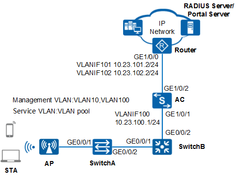
Networking Requirements
Users in the guest area of a company want to access the company's intranet through an AP. The company needs to deploy an identity authentication system for access control of users who attempt to connect to the network, preventing unauthorized access.
Because visitors move frequently, Portal authentication is configured and the RADIUS server is used to authenticate users.
Data Plan
Item |
Data |
|---|---|
Management VLANs for APs |
VLAN 10 and VLAN 100 |
Service VLAN for STAs |
VLAN pool
|
DHCP server |
The AC functions as a DHCP server to assign IP addresses to APs and STAs. |
IP address pool for APs |
10.23.10.2 to 10.23.10.254/24 |
IP address pool for STAs |
10.23.101.3 to 10.23.101.254/24 10.23.102.3 to 10.23.102.254/24 |
AC's source interface address |
VLANIF100: 10.23.100.1/24 |
RADIUS authentication parameters |
Name of the RADIUS authentication scheme: abc Name of a RADIUS server template: rd1
AAA domain: huawei.com |
Portal server template |
|
Portal access profile |
|
Authentication-free rule template |
|
Authentication profile |
|
AP group |
|
Regulatory domain profile |
|
SSID profile |
|
Security profile |
|
VAP profile |
|
Configuration Roadmap
- Configure basic WLAN services so that the AC can communicate with upstream and downstream network devices, and the AP can go online.
- Configure AAA on the AC to implement identity authentication on access users through the RADIUS server. The configuration includes configuring a RADIUS server template, an AAA scheme, and an authentication domain, and binding the RADIUS server template and AAA scheme to the authentication domain.
- Configure Portal authentication. The configuration includes configuring a Portal server template, a Portal access profile, an authentication-free rule profile, and an authentication profile, and binding the authentication profile to an interface.
- Configure WLAN service parameters, and bind a security policy profile and an authentication profile to a VAP profile to control access from STAs.
Procedure
- Configure the network devices.# Add GE0/0/1 and GE0/0/2 on SwitchA (access switch) to VLAN 10. The default VLAN of GE0/0/1 is VLAN 10.
<HUAWEI> system-view
[HUAWEI] sysname SwitchA
[SwitchA] vlan batch 10
[SwitchA] interface gigabitethernet 0/0/1
[SwitchA-GigabitEthernet0/0/1] port link-type trunk
[SwitchA-GigabitEthernet0/0/1] port trunk pvid vlan 10
[SwitchA-GigabitEthernet0/0/1] port trunk allow-pass vlan 10
[SwitchA-GigabitEthernet0/0/1] undo port trunk allow-pass vlan 1
[SwitchA-GigabitEthernet0/0/1] stp edged-port enable
[SwitchA-GigabitEthernet0/0/1] port-isolate enable
[SwitchA-GigabitEthernet0/0/1] quit
[SwitchA] interface gigabitethernet 0/0/2
[SwitchA-GigabitEthernet0/0/2] port link-type trunk
[SwitchA-GigabitEthernet0/0/2] port trunk allow-pass vlan 10
[SwitchA-GigabitEthernet0/0/2] undo port trunk allow-pass vlan 1
[SwitchA-GigabitEthernet0/0/2] quit
# Add GE0/0/1 on SwitchB (aggregation switch) to VLAN 10, and GE0/0/2 to VLAN 100. Create VLANIF 100 and set the IP address of VLANIF 100 to 10.23.100.2/24.<HUAWEI> system-view [HUAWEI] sysname SwitchB [SwitchB] vlan batch 10 100 [SwitchB] interface gigabitethernet 0/0/1 [SwitchB-GigabitEthernet0/0/1] port link-type trunk [SwitchB-GigabitEthernet0/0/1] port trunk allow-pass vlan 10 [SwitchB-GigabitEthernet0/0/1] undo port trunk allow-pass vlan 1 [SwitchB-GigabitEthernet0/0/1] quit [SwitchB] interface gigabitethernet 0/0/2 [SwitchB-GigabitEthernet0/0/2] port link-type trunk [SwitchB-GigabitEthernet0/0/2] port trunk allow-pass vlan 100 [SwitchB-GigabitEthernet0/0/2] undo port trunk allow-pass vlan 1 [SwitchB-GigabitEthernet0/0/2] quit [SwitchB] interface vlanif 100 [SwitchB-Vlanif100] ip address 10.23.100.2 24 [SwitchB-Vlanif100] quit
# On Router, add GE1/0/0 to VLAN 101 and VLAN 102. Create VLANIF 101 and VLANIF 102 and set the IP address of VLANIF 101 to 10.23.101.2/24 and the IP address of VLANIF 102 to 10.23.102.2/24.<Huawei> system-view [Huawei] sysname Router [Router] vlan batch 101 102 [Router] interface gigabitethernet 1/0/0 [Router-GigabitEthernet1/0/0] port link-type trunk [Router-GigabitEthernet1/0/0] port trunk allow-pass vlan 101 102 [Router-GigabitEthernet1/0/0] quit [Router] interface vlanif 101 [Router-Vlanif101] ip address 10.23.101.2 24 [Router-Vlanif101] quit [Router] interface vlanif 102 [Router-Vlanif102] ip address 10.23.102.2 24 [Router-Vlanif102] quit
- Configure the AC to communicate with the network devices.# Configure GE1/0/1 on the AC to VLAN 100, and GE1/0/2 to VLAN 101 and VLAN 102. Create VLANIF 100 and set the IP address of VLANIF 100 to 10.23.100.1/24.
<HUAWEI> system-view
[HUAWEI] sysname AC
[AC] vlan batch 100 101 102
[AC] interface vlanif 100
[AC-Vlanif100] ip address 10.23.100.1 24
[AC-Vlanif100] quit
[AC] interface gigabitethernet 1/0/1
[AC-GigabitEthernet1/0/1] port link-type trunk
[AC-GigabitEthernet1/0/1] port trunk allow-pass vlan 100
[AC-GigabitEthernet1/0/1] undo port trunk allow-pass vlan 1
[AC-GigabitEthernet1/0/1] quit
[AC] interface gigabitethernet 1/0/2
[AC-GigabitEthernet1/0/2] port link-type trunk
[AC-GigabitEthernet1/0/2] port trunk allow-pass vlan 101 102
[AC-GigabitEthernet1/0/2] undo port trunk allow-pass vlan 1
[AC-GigabitEthernet1/0/2] quit
# Configure a route from the AC to the APs with the next hop as SwitchB's VLANIF 100.[AC] ip route-static 10.23.10.0 24 10.23.100.2
- Configure the DHCP servers to assign IP addresses to APs and STAs.# Configure DHCP relay on SwitchB.
[SwitchB] dhcp enable
[SwitchB] interface vlanif 10
[SwitchB-Vlanif10] ip address 10.23.10.1 24
[SwitchB-Vlanif10] dhcp select relay
[SwitchB-Vlanif10] dhcp relay server-ip 10.23.100.1
[SwitchB-Vlanif10] quit
# Create VLANIF 101 and VLANIF 102 on the AC to assign IP addresses to STAs, and specify the default gateway. Configure the DNS server as required. The common methods are as follows:
- In interface address pool scenarios, run the dhcp server dns-list ip-address &<1-8> command in the VLANIF interface view.
- In global address pool scenarios, run the dns-list ip-address &<1-8> command in the IP address pool view.
[AC] dhcp enable
[AC] interface vlanif 101
[AC-Vlanif101] ip address 10.23.101.1 24
[AC-Vlanif101] dhcp select interface
[AC-Vlanif101] dhcp server gateway-list 10.23.101.2
[AC-Vlanif101] quit
[AC] interface vlanif 102
[AC-Vlanif102] ip address 10.23.102.1 24
[AC-Vlanif102] dhcp select interface
[AC-Vlanif102] dhcp server gateway-list 10.23.102.2
[AC-Vlanif102] quit
# On the AC, create a global IP address pool to allocate IP addresses to APs.[AC] ip pool huawei [AC-ip-pool-huawei] network 10.23.10.0 mask 24 [AC-ip-pool-huawei] gateway-list 10.23.10.1 [AC-ip-pool-huawei] option 43 sub-option 3 ascii 10.23.100.1 [AC-ip-pool-huawei] quit
- Configure a VLAN pool for service VLANs.# On the AC, create a VLAN pool, add VLAN 101 and VLAN 102 to the pool, and set the VLAN assignment algorithm to hash in the VLAN pool.
This example uses the VLAN assignment algorithm hash (default) as an example. If the default setting is not changed before, you do not need to run the assignment hash command.
In this example, only VLAN 101 and VLAN 102 are added to the VLAN pool. You can use the similar method to add multiple VLANs to a VLAN pool.
[AC] vlan pool sta-pool
[AC-vlan-pool-sta-pool] vlan 101 102
[AC-vlan-pool-sta-pool] assignment hash
[AC-vlan-pool-sta-pool] quit
- Configure an AP to go online.# Create an AP group to which the APs with the same configuration can be added.
[AC] wlan
[AC-wlan-view] ap-group name ap-group1
[AC-wlan-ap-group-ap-group1] quit
# Create a regulatory domain profile, configure the AC country code in the profile, and apply the profile to the AP group.[AC-wlan-view] regulatory-domain-profile name default [AC-wlan-regulate-domain-default] country-code cn [AC-wlan-regulate-domain-default] quit [AC-wlan-view] ap-group name ap-group1 [AC-wlan-ap-group-ap-group1] regulatory-domain-profile default Warning: Modifying the country code will clear channel, power and antenna gain configurations of the radio and reset the AP. Continue?[Y/N]:y [AC-wlan-ap-group-ap-group1] quit [AC-wlan-view] quit
# Configure the AC's source interface.[AC] capwap source interface vlanif 100
# Import the AP offline on the AC and add the AP to AP group ap-group1. Assume that the AP's MAC address is 60de-4476-e360. Configure a name for the AP based on the AP's deployment location, so that you can know where the AP is deployed from its name. For example, name the AP area_1 if it is deployed in Area 1. The default AP authentication mode is MAC address authentication. If the default settings are retained, you do not need to run the ap auth-mode mac-auth command.
In this example, the AP5030DN is used and has two radios: radio 0 (2.4 GHz radio) and radio 1 (5 GHz radio).
[AC] wlan
[AC-wlan-view] ap auth-mode mac-auth
[AC-wlan-view] ap-id 0 ap-mac 60de-4476-e360
[AC-wlan-ap-0] ap-name area_1
Warning: This operation may cause AP reset. Continue? [Y/N]:y
[AC-wlan-ap-0] ap-group ap-group1
Warning: This operation may cause AP reset. If the country code changes, it will clear channel, power and antenna gain configuration s of the radio, Whether to continue? [Y/N]:y
[AC-wlan-ap-0] quit
[AC-wlan-view] quit
# After the AP is powered on, run the display ap all command to check the AP state. If the State field is displayed as nor, the AP goes online successfully.[AC] display ap all Total AP information: nor : normal [1] ------------------------------------------------------------------------------------- ID MAC Name Group IP Type State STA Uptime ------------------------------------------------------------------------------------- 0 60de-4476-e360 area_1 ap-group1 10.23.10.254 AP5030DN nor 0 10S ------------------------------------------------------------------------------------- Total: 1 - Configure AAA.
# Create and configure the RADIUS server template rd1.
[AC] radius-server template rd1
[AC-radius-rd1] radius-server authentication 10.23.200.1 1812
[AC-radius-rd1] radius-server shared-key cipher Huawei@123
[AC-radius-rd1] quit
# Create the AAA authentication scheme abc and set the authentication mode to RADIUS.
[AC] aaa
[AC-aaa] authentication-scheme abc
[AC-aaa-authen-abc] authentication-mode radius
[AC-aaa-authen-abc] quit
# Create the authentication domain huawei.com, and bind the AAA authentication scheme abc and RADIUS server template rd1 to the domain.
[AC-aaa] domain huawei.com
[AC-aaa-domain-huawei.com] authentication-scheme abc
[AC-aaa-domain-huawei.com] radius-server rd1
[AC-aaa-domain-huawei.com] quit
[AC-aaa] quit
# Check whether a user can pass RADIUS authentication. (The test user test and password Huawei@123 have been configured on the RADIUS server.)
[AC] test-aaa test Huawei@123 radius-template rd1
Info: Account test succeed.
- Configure Portal authentication.# Configure the Portal server template abc.
[AC] web-auth-server abc
[AC-web-auth-server-abc] server-ip 10.23.200.1
[AC-web-auth-server-abc] port 50200
[AC-web-auth-server-abc] url http://10.23.200.1:8080/webagent
[AC-web-auth-server-abc] shared-key cipher Huawei@123
[AC-web-auth-server-abc] quit
# Configure the Portal access profile web1.[AC] portal-access-profile name web1 [AC-portal-acces-profile-web1] web-auth-server abc layer3 [AC-portal-acces-profile-web1] quit
# Configure the authentication-free rule profile default_free_rule.[AC] free-rule-template name default_free_rule [AC-free-rule-default_free_rule] free-rule 1 destination ip 10.23.201.1 mask 32 [AC-free-rule-default_free_rule] quit
# Configure the authentication profile p1, bind the Portal access profile web1, and authentication-free rule profile default_free_rule to the authentication profile, specify the domain huawei.com as the forcible authentication domain in the authentication profile, set the user access mode to multi-authen, and set the maximum number of access users to 100.
[AC] authentication-profile name p1
[AC-authen-profile-p1] portal-access-profile web1
[AC-authen-profile-p1] free-rule-template default_free_rule
[AC-authen-profile-p1] access-domain huawei.com force
[AC-authen-profile-p1] authentication mode multi-authen max-user 100
[AC-authen-profile-p1] quit
- Configure WLAN service parameters.
# Create security profile wlan-security and set the security policy in the profile. By default, the security policy is set to open system.
[AC] wlan
[AC-wlan-view] security-profile name wlan-security
[AC-wlan-sec-prof-wlan-security] quit
# Create SSID profile wlan-ssid and set the SSID name to wlan-net.
[AC-wlan-view] ssid-profile name wlan-ssid
[AC-wlan-ssid-prof-wlan-ssid] ssid wlan-net
[AC-wlan-ssid-prof-wlan-ssid] quit
# Create the VAP profile wlan-vap, configure the data forwarding mode and service VLANs, and bind the security profile, authentication profile, and SSID profile to the VAP profile.
[AC-wlan-view] vap-profile name wlan-vap
[AC-wlan-vap-prof-wlan-vap] forward-mode tunnel
[AC-wlan-vap-prof-wlan-vap] service-vlan vlan-pool sta-pool
[AC-wlan-vap-prof-wlan-vap] security-profile wlan-security
[AC-wlan-vap-prof-wlan-vap] ssid-profile wlan-ssid
[AC-wlan-vap-prof-wlan-vap] authentication-profile p1
[AC-wlan-vap-prof-wlan-vap] quit
# Bind the VAP profiles to the AP group and apply the VAP profiles to radio 0 and radio 1 of the APs.
[AC-wlan-view] ap-group name ap-group1
[AC-wlan-ap-group-ap-group1] vap-profile wlan-vap wlan 1 radio 0
[AC-wlan-ap-group-ap-group1] vap-profile wlan-vap wlan 1 radio 1
[AC-wlan-ap-group-ap-group1] quit
- Commit the configuration.
[AC-wlan-view] commit all
Warning: Committing configuration may cause service interruption, continue?[Y/N]:y
- Verify the configuration.
The WLAN with the SSID wlan-net is available for STAs after the configuration is complete.
- The STAs obtain IP addresses when they successfully associate with the WLAN.
- When a user opens the browser and attempts to access the network, the user is automatically redirected to the authentication page provided by the Portal server. After entering the correct user name and password on the page, the user can access the network.
Configuration Files
SwitchA configuration file
#
sysname SwitchA
#
vlan batch 10
#
interface GigabitEthernet0/0/1
 port link-type trunk
 port trunk pvid vlan 10
 undo port trunk allow-pass vlan 1
 port trunk allow-pass vlan 10
 stp edged-port enable
 port-isolate enable group 1
#
interface GigabitEthernet0/0/2
 port link-type trunk
 undo port trunk allow-pass vlan 1
 port trunk allow-pass vlan 10
#
return
SwitchB configuration file
#
sysname SwitchB
#
vlan batch 10 100
#
dhcp enable
#
interface Vlanif10
 ip address 10.23.10.1 255.255.255.0
 dhcp select relay
 dhcp relay server-ip 10.23.100.1
#
interface Vlanif100
 ip address 10.23.100.2 255.255.255.0
#
interface GigabitEthernet0/0/1
 port link-type trunk
 undo port trunk allow-pass vlan 1
 port trunk allow-pass vlan 10
#
interface GigabitEthernet0/0/2
 port link-type trunk
 undo port trunk allow-pass vlan 1
 port trunk allow-pass vlan 100
#
return
Router configuration file
#
sysname Router
#
vlan batch 101 to 102
#
interface Vlanif101
 ip address 10.23.101.2 255.255.255.0
#
interface Vlanif102
 ip address 10.23.102.2 255.255.255.0
#
interface GigabitEthernet1/0/0
 port link-type trunk
 port trunk allow-pass vlan 101 to 102
#
return
AC configuration file
#
 sysname AC
#
vlan batch 100 to 102
#
authentication-profile name p1
 portal-access-profile web1
 free-rule-template default_free_rule
 authentication mode multi-authen max-user 100
 access-domain huawei.com force
#
vlan pool sta-pool
 vlan 101 to 102
#
dhcp enable
#
radius-server template rd1
 radius-server shared-key cipher %^%#FQV~Lp0}JS<[2z:d"$x3f[D7U4cUr9_zs)~DgufB%^%#
 radius-server authentication 10.23.200.1 1812 weight 80
#
free-rule-template name default_free_rule
 free-rule 1 destination ip 10.23.201.1 mask 255.255.255.255
#
web-auth-server abc
 server-ip 10.23.200.1
 port 50200
 shared-key cipher  %^%#lOs#%4N$!'<=NfH!FUeI;)FY1Uc~H,@0;P<s!9>C%^%#
 url http://10.23.200.1:8080/webagent
#
portal-access-profile name web1
 web-auth-server abc layer3
#
ip pool huawei
 gateway-list 10.23.10.1
 network 10.23.10.0 mask 255.255.255.0
 option 43 sub-option 3 ascii 10.23.100.1
#
aaa
 authentication-scheme abc
  authentication-mode radius
 domain huawei.com
  authentication-scheme abc
  radius-server rd1
#
interface Vlanif100
 ip address 10.23.100.1 255.255.255.0
#
interface Vlanif101
 ip address 10.23.101.1 255.255.255.0
 dhcp select interface
 dhcp server gateway-list 10.23.101.2
#
interface Vlanif102
 ip address 10.23.102.1 255.255.255.0
 dhcp select interface
 dhcp server gateway-list 10.23.102.2
#
interface GigabitEthernet1/0/1
 port link-type trunk
 undo port trunk allow-pass vlan 1
 port trunk allow-pass vlan 100
#
interface GigabitEthernet1/0/2
 port link-type trunk
 undo port trunk allow-pass vlan 1
 port trunk allow-pass vlan 101 to 102
#
ip route-static 10.23.10.0 255.255.255.0 10.23.100.2
#
capwap source interface vlanif100
#
wlan
 security-profile name wlan-security
 ssid-profile name wlan-ssid
  ssid wlan-net
 vap-profile name wlan-vap
  forward-mode tunnel
  service-vlan vlan-pool sta-pool
  ssid-profile wlan-ssid
  security-profile wlan-security
  authentication-profile p1
 regulatory-domain-profile name default
 ap-group name ap-group1
  radio 0
   vap-profile wlan-vap wlan 1
  radio 1
   vap-profile wlan-vap wlan 1
 ap-id 0 type-id 35 ap-mac 60de-4476-e360 ap-sn 210235554710CB000042
  ap-name area_1
  ap-group ap-group1
 #
return