Configuring a Layer 3 VXLAN Gateway
Context
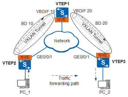
A VBDIF interface is configured on a VXLAN Layer 3 gateway to forward packets across network segments. You do not need to create a VBDIF interface for communication between users in the same network segment.
If end users in a VXLAN site need to access the Internet or communicate with end users in another VXLAN site, a VXLAN Layer 3 gateway needs to be deployed to provide end users with Layer 3 services.
In Figure 1, after you create a logical Layer 3 VBDIF interface and configure an IP address for the VBDIF interface, the VBDIF interface functions as the gateway for tenants in the BD to forward packets at Layer 3 based on the IP address. Each BD has only one VBDIF interface.
To ensure that users in different network segments can communicate with each other, ensure that the default gateway address is the IP address of the VBDIF interface on the VXLAN Layer 3 gateway.
When configuring a VXLAN Layer 3 gateway, choose configuration steps according to the Overlay network IP layer protocol.
When the Overlay network is an IPv4 network, you can choose Configuration of VXLAN Layer 3 Gateway for an IPv4 overlay network.
When the Overlay network is an IPv6 network, you can choose Configuration of VXLAN Layer 3 Gateway for an IPv6 overlay network.
Procedure
- Configuration of VXLAN Layer 3 Gateway for an IPv4 overlay network:
- Run interface vbdif bd-id
A VBDIF interface is created and the VBDIF interface view is displayed.
- Run interface vbdif bd-id
- Configuration of VXLAN Layer 3 Gateway for an IPv6 overlay network:
- Run interface vbdif bd-id
A VBDIF interface is created and the VBDIF interface view is displayed.
- Run interface vbdif bd-id
Follow-up Procedure
The S6720-EI and S6720S-EI switches can decapsulate received VXLAN packets and forward them at Layer 3 only after a VXLAN loopback interface is configured on them. As a result, you need to configure an Eth-Trunk interface as the VXLAN loopback interface when the S6720-EI and S6720S-EI switches function as the Layer 3 VXLAN gateway. Perform the configuration as follows:
Run interface eth-trunk trunk-id
The Eth-Trunk interface view is displayed.
-
The Eth-Trunk interface is configured as a VXLAN loopback interface.
By default, an Eth-Trunk interface is not a VXLAN loopback interface.
Run trunkport interface-type interface-number
A physical interface is added to the Eth-Trunk interface.

After an Eth-Trunk is configured as a VXLAN loopback interface, STP is automatically disabled on the Eth-Trunk. The Eth-Trunk then does not support STP configuration commands. After the configuration is canceled, STP is automatically enabled on the Eth-Trunk.
Only one Eth-Trunk on a switch can be configured as the VXLAN loopback interface. VXLAN packets from all VBDIF interfaces are encapsulated and decapsulated by this loopback interface.
An Eth-Trunk containing member interfaces cannot be configured as a VXLAN loopback interface.
The configurations allowed on an Eth-Trunk to be configured as a loopback interface include description, enable snmp trap updown, jumboframe enable, mixed-rate link enable, qos phb marking enable, set flow-stat interval, shutdown, local-preference enable, traffic-policy (interface view), and trust. If other configurations exist on the Eth-Trunk, the Eth-Trunk cannot be configured as a loopback interface.
After an Eth-Trunk is configured as a loopback interface, the Eth-Trunk supports only the following configurations: authentication open ucl-policy enable, description, enable snmp trap updown, jumboframe enable, mixed-rate link enable, qos phb marking enable, set flow-stat interval, shutdown, local-preference enable, statistic enable (interface view), traffic-policy (interface view), vcmp disable, and trust.
Before running the undo service type vxlan-tunnel command, delete all the member interfaces of the Eth-Trunk interface and all VBDIF interfaces on the device.