Example for Configuring Interface-based VLAN Assignment
Overview
VLAN Assignment Mode
|
Implementation | Advantage | Disadvantage | Usage Scenario |
|---|---|---|---|---|
Interface-based VLAN assignment |
VLANs are assigned based on interfaces. A network administrator preconfigures a PVID for each interface on a switch. When an untagged frame arrives at an interface, the switch adds the PVID of the interface to the frame. The frame is then transmitted in the VLAN specified by the PVID. |
It is simple to define VLAN members. |
The network administrator needs to reconfigure VLANs when VLAN members change. |
Applies to networks of any scale and with devices at fixed locations. |
MAC address-based VLAN assignment |
VLANs are assigned based on source MAC addresses of frames. A network administrator preconfigures mappings between MAC addresses and VLAN IDs. When receiving an untagged frame, the switch adds the VLAN tag mapping the MAC address of the frame to the frame. Then the frame is transmitted in the specified VLAN. |
When physical locations of users change, the network administrator does not need to reconfigure VLANs for the users. This improves security and access flexibility on a network. |
The network administrator must predefine VLANs for all members on a network. |
Applies to small-scale networks where user terminals often change physical locations but their NICs seldom change, for example, mobile computers. |
IP subnet-based VLAN assignment |
VLANs are assigned based on source IP addresses and subnet masks. A network administrator preconfigures mappings between IP addresses and VLAN IDs. When receiving an untagged frame, the switch adds the VLAN tag mapping the IP address of the frame to the frame. Then the frame is transmitted in the specified VLAN. |
|
Users are evenly spread and multiple users are on the same network segment. |
Applies to scenarios where there are high requirements for mobility and simplified management and low requirements for security. For example, this mode can be used if a PC with multiple IP addresses needs to access servers on different network segments or a PC needs to join a new VLAN automatically after the PC's IP address changes. |
Protocol-based VLAN assignment |
VLANs are assigned based on protocol (suite) types and encapsulation formats of frames. A network administrator preconfigures mappings between protocol types and VLAN IDs. When receiving an untagged frame, the switch adds the VLAN tag mapping the protocol type of the frame to the frame. The frame is then transmitted in the specified VLAN. |
This mode binds service types to VLANs, facilitating management and maintenance. |
|
Applies to networks using multiple protocols. |
Policy-based VLAN assignment (MAC addresses, IP addresses, and interfaces) |
VLANs are assigned based on policies such as combinations of interfaces, MAC addresses, and IP addresses. A network administrator preconfigures policies. When receiving an untagged frame that matches a configured policy, the switch adds a specified VLAN tag to the frame. The frame is then transmitted in the specified VLAN. |
|
Each policy needs to be manually configured. |
Applies to complex networks. |
Interface-based VLAN assignment is the simplest and most commonly used method.
Networking Requirements
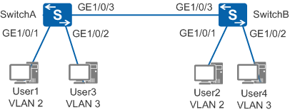
In Figure 1, the switch of an enterprise connects to many users, and users accessing the same service connect to the enterprise network through different devices. To ensure communication security and prevent broadcast storms, the enterprise requires that users using the same service communicate with each other and users accessing different services be isolated. You can configure interface-based VLAN assignment on the switch so that the switch adds interfaces connected to users using the same service to the same VLAN. Users in different VLANs cannot communicate with each other at Layer 2, and users in the same VLAN can communicate with each other.
Configuration Roadmap
The configuration roadmap is as follows:
- Create VLANs and add interfaces that connect users to VLANs to isolate Layer 2 traffic of different services.
- Configure link types of interfaces between SwitchA and SwitchB and VLANs allowed by interfaces so that users accessing the same service can communicate with each other through SwitchA and SwitchB.
Procedure
- Create VLAN 2 and VLAN 3 on SwitchA and add interfaces
that are connected to users to VLANs. The configuration of SwitchB
is similar to the configuration of SwitchA, and is not mentioned here.
<HUAWEI> system-view
[HUAWEI] sysname SwitchA
[SwitchA] vlan batch 2 3   //Create VLAN 2 and VLAN 3 in a batch.
[SwitchA] interface gigabitethernet 1/0/1
[SwitchA-GigabitEthernet1/0/1] port link-type access  //The interface connected to the access device must be the access interface. The default link type of an interface is not access, so you need to manually configure the access interface.
[SwitchA-GigabitEthernet1/0/1] port default vlan 2   //Add GE1/0/1 to VLAN 2.
[SwitchA-GigabitEthernet1/0/1] quit
[SwitchA] interface gigabitethernet 1/0/2
[SwitchA-GigabitEthernet1/0/2] port link-type access
[SwitchA-GigabitEthernet1/0/2] port default vlan 3   //Add GE1/0/2 to VLAN 3.
[SwitchA-GigabitEthernet1/0/2] quit
- Configure the link type of the interface on SwitchA that
is connected to SwitchB and VLAN allowed by the interface. The configuration
of SwitchB is similar to the configuration of SwitchA, and is not
mentioned here.
[SwitchA] interface gigabitethernet 1/0/3
[SwitchA-GigabitEthernet1/0/3] port link-type trunk   //The link type of interfaces connecting switches must be trunk. The default link type of an interface is not trunk, so you need to manually configure the trunk interface.
[SwitchA-GigabitEthernet1/0/3] port trunk allow-pass vlan 2 3    //Add GE1/0/3 to VLAN 2 and VLAN 3.
- Verify the configuration.
User1 and User2 are on the same network segment, for example, 192.168.100.0/24; User3 and User4 are on the same network segment, for example, 192.168.200.0/24.
User1 and User2 can ping each other, but cannot ping User3 or User4. User3 and User4 can ping each other, but cannot ping User1 or User2.
Configuration Files
SwitchA configuration file
#
sysname SwitchA
#
vlan batch 2 to 3
#
interface GigabitEthernet1/0/1
 port link-type access
 port default vlan 2
#
interface GigabitEthernet1/0/2
 port link-type access
 port default vlan 3
#
interface GigabitEthernet1/0/3
 port link-type trunk
 port trunk allow-pass vlan 2 to 3
#
return
SwitchB configuration file
#
sysname SwitchB
#
vlan batch 2 to 3
#
interface GigabitEthernet1/0/1
 port link-type access
 port default vlan 2
#
interface GigabitEthernet1/0/2
 port link-type access
 port default vlan 3
#
interface GigabitEthernet1/0/3
 port link-type trunk
 port trunk allow-pass vlan 2 to 3
#
return