Example for Configuring Interface-based VLAN Assignment (Access Device Used as the Gateway)
Overview
VLANs can be assigned based on interfaces, MAC addresses, IP subnets, protocols, and policies (MAC addresses, IP addresses, and interfaces). Interface-based VLAN assignment is the simplest and commonly used.
Interface-based VLAN assignment indicates that VLANs are assigned based on interfaces. A network administrator preconfigures a PVID for each interface on a switch. When an untagged frame arrives at an interface, the switch adds the PVID of the interface to the frame. Then the frame is transmitted in a specified VLAN.
In typical hierarchical networking, when the access switch is a Layer 3 switch, the access switch can be used as the gateway of PCs to simplify the configuration of the aggregation switch.
Networking Requirements
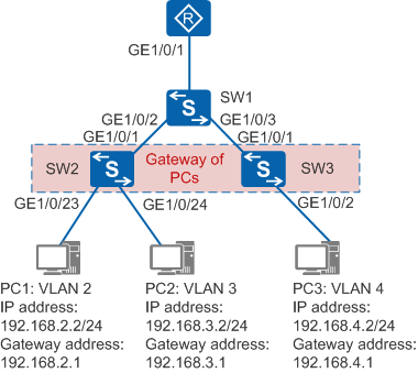
In Figure 1, PC1 and PC2 belong to VLAN 2 and VLAN 3, respectively. PC1 and PC2 connect to the aggregation switch SW1 through the access switch SW2. PC3 belongs to VLAN 4 and connects to SW1 through SW3. SW2 functions as the gateway of PC1 and PC2, and SW3 is used as the gateway of PC3. Static routes are configured on switches so that PCs can communicate with each other and can be connected to the router.
Configuration Roadmap
The configuration roadmap is as follows:
- Configure interface-based assignment on the access switch to implement Layer 2 interworking.
- Configure access switches as gateways of PCs to implement communication between PCs on different network segments.
- Configure static routes on the aggregation switch so that PCs can communicate with the router.
Procedure
- Configure SW2.
# Create VLANs.
<HUAWEI> system-view
[HUAWEI] sysname SW2  //Change the device name to SW2 for easy identification.
[SW2] vlan batch 2 to 3  //Create VLAN 2 and VLAN 3 in a batch.
# Add interfaces to VLANs.
[SW2] interface gigabitethernet 1/0/23
[SW2-GigabitEthernet1/0/23] port link-type access  //Configure the interface connected to the PC as the access interface.
[SW2-GigabitEthernet1/0/23] port default vlan 2  //Add PC1 to VLAN 2.
[SW2-GigabitEthernet1/0/23] quit
[SW2] interface gigabitethernet 1/0/24
[SW2-GigabitEthernet1/0/24] port link-type access
[SW2-GigabitEthernet1/0/24] port default vlan 3  //Add PC2 to VLAN 3.
[SW2-GigabitEthernet1/0/24] quit
# Configure VLANIF interfaces and configure IP addresses for VLANIF interfaces as gateway addresses of PCs.
[SW2] interface vlanif 2  //Create VLANIF 2.
[SW2-Vlanif2] ip address 192.168.2.1 24  //Configure an IP address for VLANIF 2. The IP address is the gateway address of PC1.
[SW2-Vlanif2] quit
[SW2] interface vlanif 3  //Create VLANIF 3.
[SW2-Vlanif3] ip address 192.168.3.1 24  //Configure an IP address for VLANIF 3. The IP address is the gateway address of PC2.
[SW2-Vlanif3] quit
# Connect SW2 to SW1.
[SW2] vlan batch 5  //Create VLAN 5.
[SW2] interface gigabitethernet 1/0/1
[SW2-GigabitEthernet1/0/1] port link-type access
[SW2-GigabitEthernet1/0/1] port default vlan 5  //Configure SW2 and SW1 to communicate in untagged mode.
[SW2-GigabitEthernet1/0/1] quit
[SW2] interface vlanif 5  //Create VLANIF 5.
[SW2-Vlanif5] ip address 192.168.5.2 24  //Configure an IP address for VLANIF 5. The IP address is the IP address of the interconnected interface between SW1 and SW2.
[SW2-Vlanif5] quit
[SW2] ip route-static 0.0.0.0 0.0.0.0 192.168.5.1  //Configure a default route so that the PC can access the router. The next hop address is the IP address of the interface connected to SW1.
- Configure SW3.
# Create VLANs.
<HUAWEI> system-view
[HUAWEI] sysname SW3  //Change the device name to SW3.
[SW3] vlan batch 4  //Create VLAN 4.
# Add interfaces to VLANs.
[SW3] interface gigabitethernet 1/0/2
[SW3-GigabitEthernet1/0/2] port link-type access  //Configure the interface connected to the PC as the access interface.
[SW3-GigabitEthernet1/0/2] port default vlan 4  //Add PC3 to VLAN 4.
[SW3-GigabitEthernet1/0/2] quit
# Configure VLANIF interfaces and configure IP addresses for VLANIF interfaces as gateway addresses of PCs.
[SW3] interface vlanif 4  //Create VLANIF 4.
[SW3-Vlanif4] ip address 192.168.4.1 24  //Configure an IP address for VLANIF 4. The IP address is the gateway address of PC3.
[SW3-Vlanif4] quit
# Connect SW3 to SW1.
[SW3] vlan batch 5  //Create VLAN 5.
[SW3] interface gigabitethernet 1/0/1
[SW3-GigabitEthernet1/0/1] port link-type access
[SW3-GigabitEthernet1/0/1] port default vlan 5  //Configure SW3 and SW1 to communicate in untagged mode.
[SW3-GigabitEthernet1/0/1] quit
[SW3] interface vlanif 5  //Create VLANIF 5.
[SW3-Vlanif5] ip address 192.168.5.3 24  //Configure an IP address for VLANIF 5. The IP address is the IP address of interconnected interface between SW3 and SW1.
[SW3-Vlanif5] quit
[SW3] ip route-static 0.0.0.0 0.0.0.0 192.168.5.1  //Configure a default route so that the PC can access the router. The next hop address is the IP address of the interface connected to SW1.
- Configure SW1.
# Create VLANs.
<HUAWEI> system-view
[HUAWEI] sysname SW1  //Change the device name to SW1.
[SW1] vlan batch 5  //Create VLAN 5.
# Add interfaces connected to PCs to VLANs.
[SW1] interface gigabitethernet 1/0/1
[SW1-GigabitEthernet1/0/1] port link-type access  //Configure the interface connected to the router as the access interface.
[SW1-GigabitEthernet1/0/1] port default vlan 5
[SW1-GigabitEthernet1/0/1] quit
[SW1] interface gigabitethernet 1/0/2
[SW1-GigabitEthernet1/0/2] port link-type access  //Configure the interface connected to SW2 as the access interface.
[SW1-GigabitEthernet1/0/2] port default vlan 5
[SW1-GigabitEthernet1/0/2] quit
[SW1] interface gigabitethernet 1/0/3
[SW1-GigabitEthernet1/0/3] port link-type access  //Configure the interface connected to SW3 as the access interface.
[SW1-GigabitEthernet1/0/3] port default vlan 5
[SW1-GigabitEthernet1/0/3] quit
# Configure VLANIF interfaces so that PCs can connect to the router.
[SW1] interface vlanif 5  //Create VLANIF 5.
[SW1-Vlanif5] ip address 192.168.5.1 24  //Configure an IP address for VLANIF 5. The IP address is the IP address of the interface connected to the router.
[SW1-Vlanif5] quit
# Configure a static route so that PCs on different network segments can communicate with each other.
[SW1] ip route-static 192.168.2.0 255.255.255.0 192.168.5.2  //Configure a static route. Packets with the destination IP address of 192.168.2.0/24 are forwarded to the next hop address of 192.168.5.2. The next hop address is the IP address of the VLANIF interface connected to SW2.
[SW1] ip route-static 192.168.3.0 255.255.255.0 192.168.5.2  //Configure a static route. Packets with the destination IP address of 192.168.3.0/24 are forwarded to the next hop address of 192.168.5.2. The next hop address is the IP address of the VLANIF interface connected to SW2.
[SW1] ip route-static 192.168.4.0 255.255.255.0 192.168.5.3  //Configure a static route. Packets with the destination IP address of 192.168.4.0/24 are forwarded to the next hop address of 192.168.5.3. The next hop address is the IP address of the VLANIF interface connected to SW3.
# Configure a default route so that PCs can communicate with the router.
[SW1] ip route-static 0.0.0.0 0.0.0.0 192.168.5.4 //The IP address is the IP address of the interface connected to SW1. - Verify the configuration.
PC1, PC2, and PC3 can access each other, and they can communicate with the router.
Configuration Files
SW1 configuration file
#
sysname SW1
#
vlan batch 5
#
interface Vlanif5
 ip address 192.168.5.1 255.255.255.0
#
interface GigabitEthernet1/0/1
 port link-type access
 port default vlan 5
#
interface GigabitEthernet1/0/2
 port link-type access
 port default vlan 5
#
interface GigabitEthernet1/0/3
 port link-type access
 port default vlan 5
#
ip route-static 0.0.0.0 0.0.0.0 192.168.5.4
ip route-static 192.168.2.0 255.255.255.0 192.168.5.2
ip route-static 192.168.3.0 255.255.255.0 192.168.5.2
ip route-static 192.168.4.0 255.255.255.0 192.168.5.3
#
return
SW2 configuration file
#
sysname SW2
#
vlan batch 2 to 3 5
#
#
interface Vlanif2
 ip address 192.168.2.1 255.255.255.0
#
interface Vlanif3
 ip address 192.168.3.1 255.255.255.0
#
interface Vlanif5
 ip address 192.168.5.2 255.255.255.0
#
interface GigabitEthernet1/0/1
 port link-type access
 port default vlan 5
#
interface GigabitEthernet1/0/23
 port link-type access
 port default vlan 2
#
interface GigabitEthernet1/0/24
 port link-type access
 port default vlan 3
#
ip route-static 0.0.0.0 0.0.0.0 192.168.5.1
#
return
SW3 configuration file
#
sysname SW3
#
vlan batch 4 to 5
#
interface Vlanif4
 ip address 192.168.4.1 255.255.255.0
#
interface Vlanif5
 ip address 192.168.5.3 255.255.255.0
#
interface GigabitEthernet1/0/1
 port link-type access
 port default vlan 5
#
interface GigabitEthernet1/0/2
 port link-type access
 port default vlan 4
#
ip route-static 0.0.0.0 0.0.0.0 192.168.5.1
#
return