Example for Directly Connecting a Terminal to a Layer 3 Gateway to Implement Inter-VLAN Communication
Overview
After VLANs are assigned, broadcast packets are only forwarded within the same VLAN. That is, hosts in different VLANs cannot communicate at Layer 2 because VLAN technology isolates broadcast domains. In real-world applications, hosts in different VLANs often need to communicate, so inter-VLAN communication needs to be implemented to resolve this. Layer 3 routing or VLAN technology is required to implement inter-VLAN communication.
VLANIF interface
A VLANIF interface is a Layer 3 logical interface. You can configure an IP address for a VLANIF interface to implement inter-VLAN Layer 3 communication.
Dot1q termination sub-interface
Similar to a VLANIF interface, a sub-interface is also a Layer 3 logical interface. You can configure dot1q termination and an IP address for a sub-interface to implement inter-VLAN Layer 3 communication.
VLANIF interfaces are the most commonly used for inter-VLAN communication due to their simple configurations. However, a VLANIF interface needs to be configured for each VLAN and each VLANIF interface requires an IP address, which wastes IP addresses.
The VLANIF interface and Dot1q termination sub-interface can only allow hosts on different network segments in different VLANs to communicate, whereas super-VLAN (VLAN aggregation) and the VLAN Switch function allow hosts on the same network segment in different VLANs to communicate.
Configuration Notes
- The default gateway address of hosts in a VLAN must be the IP address of the VLANIF interface that corresponds to the VLAN.
- This example applies to all versions of all switches.
Networking Requirements
Different user hosts of an enterprise transmit the same service, and are located on different network segments. User hosts transmitting the same service belong to different VLANs and need to communicate.
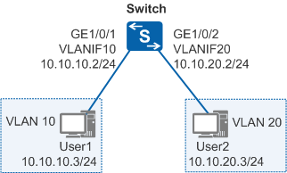
In Figure 1, User1 and User2 access the same service but belong to different VLANs and are located on different network segments. User1 and User2 need to communicate.
Configuration Roadmap
The configuration roadmap is as follows:
- Create VLANs and determine the VLANs to which users belong.
- Add interfaces to VLANs and configure the interfaces to allow the VLANs.
- Create VLANIF interfaces and configure IP addresses for the VLANIF interfaces to implement Layer 3 connectivity.
Procedure
- Configure the switch.
# Create VLANs, and configure interfaces on the switch connected to user hosts as access interfaces and add them to VLANs.
<HUAWEI> system-view
[HUAWEI] sysname Switch
[Switch] vlan batch 10 20
[Switch] interface gigabitethernet 1/0/1
[Switch-GigabitEthernet1/0/1] port link-type access   //Configure the link type of the interface as access.
[Switch-GigabitEthernet1/0/1] port default vlan 10   //Add the interface to VLAN 10.
[Switch-GigabitEthernet1/0/1] quit
[Switch] interface gigabitethernet 1/0/2
[Switch-GigabitEthernet1/0/2] port link-type access
[Switch-GigabitEthernet1/0/2] port default vlan 20
[Switch-GigabitEthernet1/0/2] quit
# Assign IP addresses to VLANIF interfaces.
[Switch] interface vlanif 10
[Switch-Vlanif10] ip address 10.10.10.2 24   //Set the IP address of VLANIF 10 to 10.10.10.2/24.
[Switch-Vlanif10] quit
[Switch] interface vlanif 20
[Switch-Vlanif20] ip address 10.10.20.2 24   //Set the IP address of VLANIF 20 to 10.10.20.2/24.
[Switch-Vlanif20] quit
- Verify the configuration.
Configure the IP address of 10.10.10.3/24 and default gateway address as 10.10.10.2/24 (VLANIF 10's IP address) for User1 in VLAN 10.
Configure the IP address of 10.10.20.3/24 and default gateway address as 10.10.20.2/24 (VLANIF 20's IP address) for User2 in VLAN 20.
After the configuration is complete, User1 in VLAN 10 and User2 in VLAN 20 can communicate.
Configuration Files
Switch configuration file
#
sysname Switch
#
vlan batch 10 20
#
interface Vlanif10
 ip address 10.10.10.2 255.255.255.0
#
interface Vlanif20
 ip address 10.10.20.2 255.255.255.0
#
interface GigabitEthernet1/0/1
 port link-type access
 port default vlan 10
#
interface GigabitEthernet1/0/2
 port link-type access
 port default vlan 20
#
return