Example for Configuring Communication Between Different Network Segments Through Static Routes
Overview
In addition to configuring an IP address for a VLANIF interface, you need to configure a static route or a dynamic routing protocol when PCs on different network segments across several switches need to communicate. This is because only a direct route is generated for the VLANIF interface's IP address on the switch and a VLANIF interface can only impalement interworking between PCs on different network segments through one switch.
Static routes can be easily configured and have low requirements on the system. They are applicable to simple, stable, and small-scale networks. However, static routes cannot automatically adapt to changes in the network topology, and manual intervention is required.
With routing algorithms, dynamic routing protocols can automatically adapt to changes in the network topology. They are applicable to the network where some Layer 3 devices are deployed. The configurations of dynamic routes are complex. Dynamic routes have higher requirements on the system than static ones and consume more network and system resources.
Networking Requirements
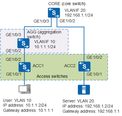
In Figure 1, to ensure security and facilitate management, an enterprise assigns a VLAN for a server. The user device belongs to VLAN 10, and the server belongs to VLAN 20. Access, aggregation, and core switches are deployed between the user and server. Access switches are layer 2 switches, and aggregation and core switches are Layer 3 switches. The user and server need to communicate with each other due to service requirements.
Configuration Roadmap
The configuration roadmap is as follows:
- Configure interface-based VLAN assignment to implement Layer 2 communication.
- Configure VLANIF 10 on the aggregation switch AGG and configure an IP address for VLANIF 10 as the gateway address of the user; configure VLANIF 20 on the core switch CORE and configure an IP address for VLANIF 20 as the gateway address of the server.
- On the aggregation switch AGG, configure a static route from AGG to the network segment of VLANIF 20; on the core switch CORE, configure a static route from CORE to the network segment of VLANIF 10. The communication across network segments is therefore implemented.
Procedure
- Configure the access switch ACC1.
# Create VLANs.
<HUAWEI> system-view
[HUAWEI] sysname ACC1  //Change the device name to ACC1 for easy identification.
[ACC1] vlan batch 10  //Create VLAN 10 in a batch.
# Add interfaces to VLANs.
[ACC1] interface gigabitethernet 1/0/1
[ACC1-GigabitEthernet1/0/1] port link-type access  //Configure the interface connected to a user host as the access interface.
[ACC1-GigabitEthernet1/0/1] port default vlan 10  //Add the user device to VLAN 10.
[ACC1-GigabitEthernet1/0/1] quit
[ACC1] interface gigabitethernet 1/0/2
[ACC1-GigabitEthernet1/0/2] port link-type trunk  //Configure the interface connected to the aggregation switch as the trunk interface.
[ACC1-GigabitEthernet1/0/2] port trunk allow-pass vlan 10  //Add the interface connected to the aggregation switch to VLAN 10.
[ACC1-GigabitEthernet1/0/2] quit
- Configure the access switch ACC2.
# Create VLANs.
<HUAWEI> system-view
[HUAWEI] sysname ACC2  //Change the device name to ACC2.
[ACC2] vlan batch 20  //Create VLAN 20 in a batch.
# Add interfaces to VLANs.
[ACC2] interface gigabitethernet 1/0/1
[ACC2-GigabitEthernet1/0/1] port link-type access  //Configure the interface connected to the server as the access interface.
[ACC2-GigabitEthernet1/0/1] port default vlan 20  //Add the user device to VLAN 20.
[ACC2-GigabitEthernet1/0/1] quit
[ACC2] interface gigabitethernet 1/0/2
[ACC2-GigabitEthernet1/0/2] port link-type trunk  //Configure the interface connected to the core switch as the trunk interface.
[ACC2-GigabitEthernet1/0/2] port trunk allow-pass vlan 20  //Add the interface connected to the core switch to VLAN 20.
[ACC2-GigabitEthernet1/0/2] quit
- Configure the aggregation switch AGG.
# Create VLANs.
<HUAWEI> system-view
[HUAWEI] sysname AGG  //Change the device name to AGG.
[AGG] vlan batch 10 30  //Create VLAN 10 and VLAN 30 in a batch.
# Add interfaces to VLANs.
[AGG] interface gigabitethernet 1/0/2
[AGG-GigabitEthernet1/0/2] port link-type trunk  //Configure the interface as the trunk interface.
[AGG-GigabitEthernet1/0/2] port trunk allow-pass vlan 10  //Add the interface to VLAN 10.
[AGG-GigabitEthernet1/0/2] quit
[AGG] interface gigabitethernet 1/0/3
[AGG-GigabitEthernet1/0/3] port link-type trunk  //Configure the interface as the trunk interface.
[AGG-GigabitEthernet1/0/3] port trunk allow-pass vlan 30  //Add the interface connected to the core switch to VLAN 30.
[AGG-GigabitEthernet1/0/3] quit
# Create VLANIF 10 and configure an IP address for VLANIF 10 as the gateway address.
[AGG] interface vlanif 10  //Create VLANIF 10.
[AGG-Vlanif10] ip address 10.1.1.1 24  //Configure an IP address for VLANIF 10. The IP address is the gateway address.
[AGG-Vlanif10] quit
# Create VLANIF 30 and configure an IP address for VLANIF 30.
[AGG] interface vlanif 30  //Create VLANIF 30.
[AGG-Vlanif30] ip address 10.10.30.1 24  //Configure an IP address for VLANIF 30. The IP address cannot conflict with IP addresses of the user and server.
[AGG-Vlanif30] quit
# Configure a static route so that the PC can access the server.
[AGG] ip route-static 192.168.1.0 255.255.255.0 10.10.30.2 //Configure a static route. The packets with the destination IP address of 192.168.1.0/24 are forwarded to the IP address 10.10.30.2 of VLANIF 30 on the core switch. - Configure the core switch CORE.
# Create VLANs.
<HUAWEI> system-view
[HUAWEI] sysname CORE  //Change the device name to CORE.
[CORE] vlan batch 20 30  //Create VLAN 20 and VLAN 30 in a batch.
# Add interfaces to VLANs.
[CORE] interface gigabitethernet 1/0/2
[CORE-GigabitEthernet1/0/2] port link-type trunk  //Configure the interface as the trunk interface.
[CORE-GigabitEthernet1/0/2] port trunk allow-pass vlan 20  //Add the interface to VLAN 20.
[CORE-GigabitEthernet1/0/2] quit
[CORE] interface gigabitethernet 1/0/3
[CORE-GigabitEthernet1/0/3] port link-type trunk  //Configure the interface as the trunk interface.
[CORE-GigabitEthernet1/0/3] port trunk allow-pass vlan 30  //Add the interface to VLAN 30.
[CORE-GigabitEthernet1/0/3] quit
# Create VLANIF 20 and configure an IP address for VLANIF 20 as the gateway address of the server.
[CORE] interface vlanif 20  //Create VLANIF 20.
[CORE-Vlanif20] ip address 192.168.1.1 24  //Configure an IP address for VLANIF 20. The IP address is the gateway address of the server.
[CORE-Vlanif20] quit
# Create VLANIF 30 and configure an IP address for VLANIF 30.
[CORE] interface vlanif 30  //Create VLANIF 30.
[CORE-Vlanif30] ip address 10.10.30.2 24  //Configure an IP address for VLANIF 30.
[CORE-Vlanif30] quit
# Configure a static route so that the server and PC can access each other.
[CORE] ip route-static 10.1.1.0 255.255.255.0 10.10.30.1 //Configure a static route. The packets with the destination IP address of 10.1.1.0/24 are forwarded to the IP address 10.10.30.1 of VLANIF 30 on the aggregation switch. - Verify the configuration.
Configure the IP address of 10.1.1.2/24 for the PC in VLAN 10 and the default gateway address as 10.1.1.1 (VLANIF 10's IP address).
Configure the IP address of 192.168.1.2/24 for the server in VLAN 20 and the default gateway address as 192.168.1.1 (VLANIF 20's IP address).
After the configuration is complete, the PC in VLAN 10 and the server in VLAN 20 can access each other.
Configuration Files
ACC1 configuration file
#
sysname ACC1
#
vlan batch 10
#
interface GigabitEthernet1/0/1
 port link-type access
 port default vlan 10
#
interface GigabitEthernet1/0/2
 port link-type trunk
 port trunk allow-pass vlan 10
#
return
ACC2 configuration file
#
sysname ACC2
#
vlan batch 20
#
interface GigabitEthernet1/0/1
 port link-type access
 port default vlan 20
#
interface GigabitEthernet1/0/2
 port link-type trunk
 port trunk allow-pass vlan 20
#
return
AGG configuration file
#
sysname AGG
#
vlan batch 10 30
#
interface Vlanif10
 ip address 10.1.1.1 255.255.255.0
#
interface Vlanif30
 ip address 10.10.30.1 255.255.255.0
#
interface GigabitEthernet1/0/2
 port link-type trunk
 port trunk allow-pass vlan 10
#
interface GigabitEthernet1/0/3
 port link-type trunk
 port trunk allow-pass vlan 30
#
ip route-static 192.168.1.0 255.255.255.0 10.10.30.2
#
return
CORE configuration file
#
sysname CORE
#
vlan batch 20 30
#
interface Vlanif20
 ip address 192.168.1.1 255.255.255.0
#
interface Vlanif30
 ip address 10.10.30.2 255.255.255.0
#
interface GigabitEthernet1/0/2
 port link-type trunk
 port trunk allow-pass vlan 20
#
interface GigabitEthernet1/0/3
 port link-type trunk
 port trunk allow-pass vlan 30
#
ip route-static 10.1.1.0 255.255.255.0 10.10.30.1
#
return