Example for Configuring MUX VLAN to Isolate Users in the Same VLAN
MUX VLAN Overview
Multiplex VLAN (MUX VLAN) provides a mechanism to control network resources using VLANs. It can implement inter-VLAN communication and intra-VLAN isolation. The MUX VLAN is often used in enterprises and in hotels and residential buildings requiring broadband access. An enterprise, hotel, or residential building shares the same VLAN, but each department, room, or household is isolated.
MUX VLAN is configured on a Layer 2 switch, whereas super-VLAN technology is configured on a Layer 3 switch. MUX VLAN is more flexible in access control, but its configuration is complex.
Configuration Notes
- The VLAN ID assigned to a principal VLAN cannot be used to configure the super-VLAN or sub-VLAN. Additionally, it is not recommended that this VLAN ID be used to configure VLAN mapping and VLAN stacking.
- The VLAN ID assigned to a group or separate VLAN cannot be used to configure a VLANIF interface, super-VLAN, or sub-VLAN. Additionally, it is not recommended that this VLAN ID be used to configure VLAN mapping and VLAN stacking.
- Disabling MAC address learning or limiting the number of learned MAC addresses on an interface affects the MUX VLAN function on the interface.
- MUX VLAN and port security cannot be configured on the same interface simultaneously.
- MUX VLAN and MAC address authentication cannot be configured on the same interface simultaneously.
- MUX VLAN and 802.1x authentication cannot be configured on the same interface simultaneously.
- If the MUX VLAN function is enabled on an interface, VLAN mapping and VLAN stacking cannot be configured on the interface.
- This example applies to all versions of all switches.
Networking Requirements
All employees of an enterprise can access servers on the enterprise network. The enterprise allows some employees to communicate but isolates other employees.
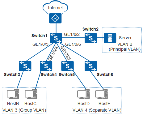
In Figure 1, Switch1 is deployed at the aggregation layer and used as the gateway for downstream hosts. Switch2, Switch3, Switch4, Switch5, and Switch6 are access switches. Their GE1/0/1 interfaces connect to downstream hosts, and their GE1/0/2 interfaces connect to Switch1. You can configure MUX VLAN on Switch1. This reduces the number of VLAN IDs on the enterprise network and facilitates network management.
Configuration Roadmap
The configuration roadmap is as follows:
Configure the principal VLAN and a VLANIF interface. The IP address of the VLANIF interface is used as the gateway IP address for downstream hosts and servers.
Configure the group VLAN.
Configure the separate VLAN.
Add interfaces to VLANs and enable the MUX VLAN function on the interfaces.
Add interfaces of access switches to VLANs.
Procedure
- Enable the MUX VLAN function on Switch1.
# On Switch1, create VLAN 2, VLAN 3, and VLAN 4, and a VLANIF interface for VLAN 2. The IP address of the VLANIF interface is used as the gateway IP address for downstream hosts and servers.
<HUAWEI> system-view
[HUAWEI] sysname Switch1
[Switch1] vlan batch 2 3 4
[Switch1] interface vlanif 2
[Switch1-Vlanif2] ip address 192.168.100.100 24
[Switch1-Vlanif2] quit
# Configure the group VLAN and separate VLAN of the MUX VLAN on Switch1.
[Switch1] vlan 2
[Switch1-vlan2] mux-vlan
[Switch1-vlan2] subordinate group 3   //Configure VLAN 3 as the group VLAN.
[Switch1-vlan2] subordinate separate 4   //Configure VLAN 4 as the separate VLAN.
[Switch1-vlan2] quit
# Add interfaces to the VLANs on Switch1 and enable the MUX VLAN function on interfaces.
[Switch1] interface gigabitethernet 1/0/2
[Switch1-GigabitEthernet1/0/2] port link-type trunk
[Switch1-GigabitEthernet1/0/2] port trunk allow-pass vlan 2
[Switch1-GigabitEthernet1/0/2] port mux-vlan enable vlan 2   //In V200R003C00 and earlier versions, you do not need to specify the VLAN. An interface can only join the MUX VLAN or Separate VLAN, or a group VLAN.
[Switch1-GigabitEthernet1/0/2] quit
[Switch1] interface gigabitethernet 1/0/3
[Switch1-GigabitEthernet1/0/3] port link-type trunk
[Switch1-GigabitEthernet1/0/3] port trunk allow-pass vlan 3
[Switch1-GigabitEthernet1/0/3] port mux-vlan enable vlan 3
[Switch1-GigabitEthernet1/0/3] quit
[Switch1] interface gigabitethernet 1/0/4
[Switch1-GigabitEthernet1/0/4] port link-type trunk
[Switch1-GigabitEthernet1/0/4] port trunk allow-pass vlan 3
[Switch1-GigabitEthernet1/0/4] port mux-vlan enable vlan 3
[Switch1-GigabitEthernet1/0/4] quit
[Switch1] interface gigabitethernet 1/0/5
[Switch1-GigabitEthernet1/0/5] port link-type trunk
[Switch1-GigabitEthernet1/0/5] port trunk allow-pass vlan 4
[Switch1-GigabitEthernet1/0/5] port mux-vlan enable vlan 4
[Switch1-GigabitEthernet1/0/5] quit
[Switch1] interface gigabitethernet 1/0/6
[Switch1-GigabitEthernet1/0/6] port link-type trunk
[Switch1-GigabitEthernet1/0/6] port trunk allow-pass vlan 4
[Switch1-GigabitEthernet1/0/6] port mux-vlan enable vlan 4
[Switch1-GigabitEthernet1/0/6] quit
- Configure interfaces of access switches and add them to
VLANs. The configurations of Switch3, Switch4, Switch5, and Switch6
are similar to the configuration of Switch2, and are not mentioned
here.
<HUAWEI> system-view
[HUAWEI] sysname Switch2
[Switch2] vlan batch 2
[Switch2] interface gigabitethernet 1/0/1
[Switch2-GigabitEthernet1/0/1] port link-type access   //Configure the link type of the interface as access.
[Switch2-GigabitEthernet1/0/1] port default vlan 2
[Switch2-GigabitEthernet1/0/1] quit
[Switch2] interface gigabitethernet 1/0/2
[Switch2-GigabitEthernet1/0/2] port link-type trunk
[Switch2-GigabitEthernet1/0/2] port trunk allow-pass vlan 2   //Configure the link type of the interface as trunk.
[Switch2-GigabitEthernet1/0/2] quit
- Verify the configuration.
The server can communicate with HostB, HostC, HostD, and HostE.
HostB can communicate with HostC.
HostD cannot communicate with HostE.
HostB and HostC cannot communicate with either HostD or HostE.
Configuration Files
Switch1 configuration file
#
sysname Switch1
#
vlan batch 2 to 4
#
vlan 2
 mux-vlan
 subordinate separate 4
 subordinate group 3
#
interface Vlanif2
 ip address 192.168.100.100 255.255.255.0
#
interface GigabitEthernet1/0/2
 port link-type trunk
 port trunk allow-pass vlan 2
 port mux-vlan enable vlan 2
#
interface GigabitEthernet1/0/3
 port link-type trunk
 port trunk allow-pass vlan 3
 port mux-vlan enable vlan 3
#
interface GigabitEthernet1/0/4
 port link-type trunk
 port trunk allow-pass vlan 3
 port mux-vlan enable vlan 3
#
interface GigabitEthernet1/0/5
 port link-type trunk
 port trunk allow-pass vlan 4
 port mux-vlan enable vlan 4
#
interface GigabitEthernet1/0/6
 port link-type trunk
 port trunk allow-pass vlan 4
 port mux-vlan enable vlan 4
#
return
Switch2 configuration file
#
sysname Switch2
#
vlan batch 2
#
interface GigabitEthernet1/0/1
 port link-type access
 port default vlan 2
#
interface GigabitEthernet1/0/2
 port link-type trunk
 port trunk allow-pass vlan 2
#
return
Switch3 configuration file
#
sysname Switch3
#
vlan batch 3
#
interface GigabitEthernet1/0/1
 port link-type access
 port default vlan 3
#
interface GigabitEthernet1/0/2
 port link-type trunk
 port trunk allow-pass vlan 3
#
return
Switch4 configuration file
#
sysname Switch4
#
vlan batch 3
#
interface GigabitEthernet1/0/1
 port link-type access
 port default vlan 3
#
interface GigabitEthernet1/0/2
 port link-type trunk
 port trunk allow-pass vlan 3
#
return
Switch5 configuration file
#
sysname Switch5
#
vlan batch 4
#
interface GigabitEthernet1/0/1
 port link-type access
 port default vlan 4
#
interface GigabitEthernet1/0/2
 port link-type trunk
 port trunk allow-pass vlan 4
#
return
Switch6 configuration file
#
sysname Switch6
#
vlan batch 4
#
interface GigabitEthernet1/0/1
 port link-type access
 port default vlan 4
#
interface GigabitEthernet1/0/2
 port link-type trunk
 port trunk allow-pass vlan 4
#
return