Example for Configuring the Super-VLAN
Super-VLAN Overview
Super-VLAN, also called VLAN aggregation, reduces the number of required IP addresses, isolates broadcast storms, and controls Layer 2 access on interfaces. A super-VLAN can be associated with multiple sub-VLANs, which are isolated at Layer 2. All sub-VLANs use the IP address of the corresponding VLANIF interface for the super-VLAN to implement Layer 3 connectivity with an external network, thereby reducing the number of IP addresses required.
The super-VLAN applies to scenarios where many users and VLANs exist, IP addresses of devices in many VLANs are on the same network segment, and inter-VLAN Layer 2 isolation needs to be implemented. Inter-VLAN proxy ARP can be enabled to implement inter-VLAN communication. For example, this can be used in hotels and residential buildings requiring broadband access. A room or household is assigned a VLAN and isolated. An IP network segment cannot be allocated to each VLAN because IP addresses are finite and there are many VLANs. The VLANs can only share an IP network segment. Assume that the IP network segment of VLAN 10 is 10.10.10.0/24. A household may use only one or two IP addresses; however, over 200 IP addresses are consumed. Super-VLAN technology allows users in VLANs 11 to 100 to share the IP network segment of 10.10.10.0/24, thereby reducing the number of IP addresses required.
Super-VLAN is Layer 3 technology configured on a Layer 3 switch, whereas MUX VLAN is configured on a Layer 2 switch. The MUX VLAN is more complex to configure than super-VLAN, but its access control is more flexible. When the switch queries temporarily offline users in the super-VLAN, the gateway needs to broadcast packets in each sub-VLAN, consuming many CPU resources.
Configuration Notes
- VLAN 1 cannot be configured as a super-VLAN.
- No physical interface can be added to a VLAN configured as a super-VLAN.
For applicable product models and versions, see Applicable Product Models and Versions.

For details about software mappings, visit Hardware Query Tool and search for the desired product model.
Networking Requirements
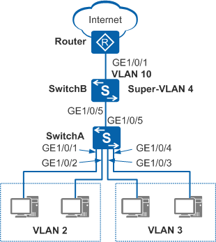
In Figure 1, a company has many departments on the same network segment. To improve service security, the company assigns different departments to different VLANs. VLAN 2 and VLAN 3 belong to different departments. Each department wants to access the Internet, and PCs in different departments need to communicate.
Configuration Roadmap
Configure VLAN aggregation on SwitchB to add VLANs of different departments to a super-VLAN so that PCs in different departments can access the Internet using the super-VLAN. Deploy proxy ARP in the super-VLAN so that PCs in different departments can communicate. The configuration roadmap is as follows:
- Configure VLANs and interfaces on SwitchA and SwitchB, add PCs of different departments to different VLANs, and configure interfaces on SwitchA and SwitchB to transparently transmit packets from VLANs.
- Configure a super-VLAN, a VLANIF interface, and a static route on SwitchB so that PCs in different departments can access the Internet.
- Configure proxy ARP in the super-VLAN on SwitchB so that PCs in different departments can communicate at Layer 3.
Procedure
- Configure SwitchA.
# Add GE1/0/1, GE1/0/2, GE1/0/3, and GE1/0/4 to VLANs.
<HUAWEI> system-view
[HUAWEI] sysname SwitchA
[SwitchA] vlan batch 2 to 3
[SwitchA] interface gigabitethernet 1/0/1
[SwitchA-GigabitEthernet1/0/1] port link-type access   //Configure the link type of the interface as access.
[SwitchA-GigabitEthernet1/0/1] port default vlan 2   //Add the interface to VLAN 2.
[SwitchA-GigabitEthernet1/0/1] quit
[SwitchA] interface gigabitethernet 1/0/2
[SwitchA-GigabitEthernet1/0/2] port link-type access
[SwitchA-GigabitEthernet1/0/2] port default vlan 2
[SwitchA-GigabitEthernet1/0/2] quit
[SwitchA] interface gigabitethernet 1/0/3
[SwitchA-GigabitEthernet1/0/3] port link-type access
[SwitchA-GigabitEthernet1/0/3] port default vlan 3   //Add the interface to VLAN 3.
[SwitchA-GigabitEthernet1/0/3] quit
[SwitchA] interface gigabitethernet 1/0/4
[SwitchA-GigabitEthernet1/0/4] port link-type access
[SwitchA-GigabitEthernet1/0/4] port default vlan 3
[SwitchA-GigabitEthernet1/0/4] quit
# Configure GE1/0/5 to transparently transmit packets from VLAN 2 and VLAN 3.
[SwitchA] interface gigabitethernet 1/0/5
[SwitchA-GigabitEthernet1/0/5] port link-type trunk
[SwitchA-GigabitEthernet1/0/5] port trunk allow-pass vlan 2 to 3
[SwitchA-GigabitEthernet1/0/5] quit
- Configure SwitchB.
# Create VLAN 2, VLAN 3, VLAN 4, and VLAN 10 and configure the interface of SwitchB connected to SwitchA to transparently transmit packets from VLAN 2 and VLAN 3 to SwitchB.
<HUAWEI> system-view
[HUAWEI] sysname SwitchB
[SwitchB] vlan batch 2 3 4 10
[SwitchB] interface gigabitethernet 1/0/5
[SwitchB-GigabitEthernet1/0/5] port link-type trunk
[SwitchB-GigabitEthernet1/0/5] port trunk allow-pass vlan 2 3
[SwitchB-GigabitEthernet1/0/5] quit
# Configure super-VLAN 4 on SwitchB and add VLAN 2 and VLAN 3 to super-VLAN 4 as sub-VLANs.
[SwitchB] vlan 4
[SwitchB-vlan4] aggregate-vlan
[SwitchB-vlan4] access-vlan 2 to 3
[SwitchB-vlan4] quit
# Create and configure VLANIF 4 so that PCs in different departments can access the Internet using super-VLAN 4.
[SwitchB] interface vlanif 4
[SwitchB-Vlanif4] ip address 10.1.1.1 24
[SwitchB-Vlanif4] quit
# Configure the uplink interface GE1/0/1 to transparently transmit packets from the VLAN that SwitchB and router belong to.
[SwitchB] interface gigabitethernet 1/0/1
[SwitchB-GigabitEthernet1/0/1] port link-type trunk
[SwitchB-GigabitEthernet1/0/1] port trunk allow-pass vlan 10
[SwitchB-GigabitEthernet1/0/1] quit
# Create and configure VLANIF 10 and specify the IP address of VLANIF 10 as the IP address for connecting SwitchB and the router.
[SwitchB] interface vlanif 10
[SwitchB-Vlanif10] ip address 10.10.1.1 24
[SwitchB-Vlanif10] quit
# Configure a static route to the router on SwitchB so that users can access the Internet.
[SwitchB] ip route-static 0.0.0.0 0.0.0.0 10.10.1.2
Configure the router interface connected to SwitchB and assign the IP address of 10.10.1.2 to the router interface. See the router configuration manual.
- Assign IP addresses to PCs.
Configure IP addresses for PCs and ensure that their IP addresses are on the same network segment as 10.1.1.1/24 (IP address of VLANIF 4).
After the configuration is complete, PCs in each department can access the Internet, but PCs in VLAN 2 and VLAN 3 cannot ping each other.
- Configure proxy ARP.
# Configure proxy ARP in super-VLAN 4 on SwitchB so that users in different departments can communicate at Layer 3.
[SwitchB] interface vlanif 4
[SwitchB-Vlanif4] arp-proxy inter-sub-vlan-proxy enable
[SwitchB-Vlanif4] quit
- Verify the configuration.
After the configuration is complete, users in VLAN 2 and VLAN 3 can ping each other and access the Internet.
Configuration Files
SwitchA configuration file
#
sysname SwitchA
#
vlan batch 2 to 3
#
interface GigabitEthernet1/0/1
 port link-type access
 port default vlan 2
#
interface GigabitEthernet1/0/2
 port link-type access
 port default vlan 2
#
interface GigabitEthernet1/0/3
 port link-type access
 port default vlan 3
#
interface GigabitEthernet1/0/4
 port link-type access
 port default vlan 3
#
interface GigabitEthernet1/0/5
 port link-type trunk
 port trunk allow-pass vlan 2 to 3
#
return
SwitchB configuration file
#
sysname SwitchB
#
vlan batch 2 to 4 10
#
vlan 4
 aggregate-vlan
 access-vlan 2 to 3
#
interface Vlanif4
 ip address 10.1.1.1 255.255.255.0
 arp-proxy inter-sub-vlan-proxy enable
#
interface Vlanif10
 ip address 10.10.1.1 255.255.255.0
#
interface GigabitEthernet1/0/1
 port link-type trunk
 port trunk allow-pass vlan 10
#
interface GigabitEthernet1/0/5
 port link-type trunk
 port trunk allow-pass vlan 2 to 3
#
ip route-static 0.0.0.0 0.0.0.0 10.10.1.2
#
return
Applicable Product Models and Versions
Product |
Product Model |
Software Version |
|---|---|---|
S2700 |
S2752EI |
V100R006C05 |
S3700 |
S3700-SI, S3700-EI |
V100R006C05 |
S3700-HI |
V200R001C00 |
|
S5700 |
S5700-EI |
V200R001(C00&C01), V200R002C00, V200R003C00, V200R005(C00&C01&C02&C03) |
S5700-SI |
V200R001C00, V200R002C00, V200R003C00, V200R005C00 |
|
S5700-HI |
V200R001(C00&C01), V200R002C00, V200R003C00, V200R005(C00SPC500&C01&C02) |
|
S5710-EI |
V200R001C00, V200R002C00, V200R003C00, V200R005(C00&C02) |
|
S5720-EI |
V200R007C00, V200R008C00, V200R009C00, V200R010C00, V200R011C00, V200R011C10, V200R012C00, V200R013C00, V200R019C00, V200R019C10 |
|
S5720-SI, S5720S-SI |
V200R008C00, V200R009C00, V200R010C00, V200R011C00, V200R011C10, V200R012C00, V200R013C00, V200R019C00, V200R019C10 |
|
S5720I-SI |
V200R012C00, V200R013C00, V200R019C00, V200R019C10 |
|
S5710-HI |
V200R003C00, V200R005(C00&C02&C03) |
|
S5720-HI |
V200R006C00, V200R007(C00&C10), V200R008C00, V200R009C00, V200R010C00, V200R011C00, V200R011C10, V200R012C00, V200R013C00, V200R019C00, V200R019C10 |
|
S5730-HI |
V200R012C00, V200R013C00, V200R019C00, V200R019C10 |
|
S5730-SI |
V200R011C10, V200R012C00, V200R013C00, V200R019C00, V200R019C10 |
|
S5730S-EI |
V200R011C10, V200R012C00, V200R013C00, V200R019C00, V200R019C10 |
|
S5731-H |
V200R013C02, V200R019C00, V200R019C10 |
|
S5731-S, S5731S-S |
V200R019C00, V200R019C10 |
|
S5731S-H |
V200R019C00, V200R019C10 |
|
S5732-H |
V200R019C00, V200R019C10 |
|
S5735-S, S5735S-S |
V200R019C00, V200R019C10 |
|
S5700 |
S5735-S-I |
V200R019C10 |
S6700 |
S6700-EI |
V200R001(C00&C01), V200R002C00, V200R003C00, V200R005(C00&C01&C02) |
S6720-EI |
V200R008C00, V200R009C00, V200R010C00, V200R011C00, V200R011C10, V200R012C00, V200R013C00, V200R019C00, V200R019C10 |
|
S6720S-EI |
V200R009C00, V200R010C00, V200R011C00, V200R011C10, V200R012C00, V200R013C00, V200R019C00, V200R019C10 |
|
S6720-SI, S6720S-SI |
V200R011C00, V200R011C10, V200R012C00, V200R013C00, V200R019C00, V200R019C10 |
|
S6720-HI |
V200R012C00, V200R013C00, V200R019C00, V200R019C10 |
|
S6730-H |
V200R013C02, V200R019C00, V200R019C10 |
|
S6730S-H |
V200R019C10 |
|
S6730-S, S6730S-S |
V200R019C00, V200R019C10 |
|
S7700 |
S7703, S7706, S7712 |
V200R001(C00&C01), V200R002C00, V200R003C00, V200R005C00, V200R006C00, V200R007C00, V200R008C00, V200R009C00, V200R010C00, V200R011C10, V200R012C00, V200R013C00, V200R013C02, V200R019C00, V200R019C10 |
S7703 PoE |
V200R013C00, V200R019C00, V200R019C10 |
|
S7706 PoE |
V200R013C00, V200R019C00, V200R019C10 |
|
S9700 |
S9703, S9706, S9712 |
V200R001(C00&C01), V200R002C00, V200R003C00, V200R005C00, V200R006C00, V200R007(C00&C10), V200R008C00, V200R009C00, V200R010C00, V200R011C10, V200R012C00, V200R013C00 |