VXLAN Network Architecture
VXLAN is an NVO3 network virtualization technology that encapsulates data packets sent from original hosts into UDP packets and encapsulates IP and MAC addresses used on the physical network in outer headers before sending the packets over an IP network. The virtual tunnel endpoint (VTEP) then decapsulates the packets and sends the packets to the destination host.
By leveraging VXLAN, a virtual network can accommodate a large number of tenants. Tenants can plan their own virtual networks without being limited by physical network IP addresses or broadcast domains. This technology significantly simplifies network management, allows VMs to migrate over a large Layer 2 network, and isolates tenants in a virtual.
Similar to a traditional VLAN, a VXLAN also allows for intra- and inter-VXLAN communication.
Intra-VXLAN Communication
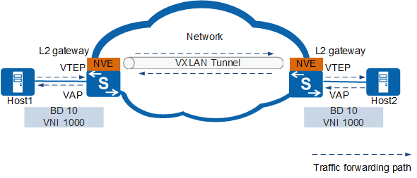
VXLAN technology constructs a virtual Layer 2 network over a Layer 3 network, implementing Layer 2 communication between VMs. Figure 1 shows intra-VXLAN communication.
Involved concepts
VXLAN Network Identifier (VNI)
A VNI is similar to a VLAN ID on a traditional network, and it identifies a VXLAN segment. Tenants on different VXLAN segments cannot communicate at Layer 2. One tenant may have one or more VNIs. A VNI consists of 24 bits and supports up to 16 million tenants.
Broadcast Domain (BD)
Similar to VLANs divided on a traditional network, BD is used for broadcast domain division on a VXLAN.
On a VXLAN, to allow Layer 2 communication between VMs in a BD, VNIs and BDs are mapped in 1:1 mode.
VXLAN VTEP
A VTEP encapsulates and decapsulates VXLAN packets.
The source and destination IP addresses in a VXLAN packet are the IP addresses of the local and remote VTEPs, respectively. A pair of VTEP addresses defines one VXLAN tunnel. A source VTEP encapsulates packets and selects a tunnel to forward them. The corresponding destination VTEP decapsulates the received packets.
Virtual Access Point (VAP)
A VAP is a VXLAN service access point used for service access based on VLANs or packet encapsulation modes. For more information, see Packet Identification:- Service access based on VLANs: The 1:1 or N:1 mapping between VLANs and BDs is configured on VTEPs. When a VTEP receives a service packet, it forwards the packet in a BD based on the mapping between VLANs and BDs.
- Service access based on packet encapsulation modes: Layer 2 sub-interfaces are created on a downlink physical interface of a VTEP, and different encapsulation modes are configured for these sub-interfaces to enable different interfaces to receive different data packets. The 1:1 mapping between Layer 2 sub-interfaces and BDs is also defined. Then service packets are sent to specific Layer 2 sub-interfaces after reaching the VTEP. That is, packets are forwarded in a BD based on the mapping between Layer 2 sub-interfaces and BDs.
Network Virtualization Edge (NVE)
An NVE is a network entity used to implement network virtualization functions. After packets are encapsulated and decapsulated through NVEs, a Layer 2 VXLAN can be established between NVEs over the basic Layer 3 network.
Layer 2 gateway
Similar to a Layer 2 access device on a traditional network, it allows tenant access to VXLANs and intra-subnet VXLAN communication in the same network segment.
Inter-VXLAN Network Communication (Centralized Gateway)
VMs in different BDs cannot directly communicate at Layer 2. VXLAN Layer 3 gateways need to be configured to implement Layer 3 communication between VMs. Figure 2 shows inter-VLAN communication.
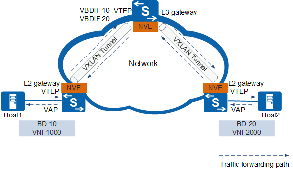
Layer 3 gateway
On a traditional network, users in different VLANs cannot directly communication at Layer 2. Layer 2 communication is also not allowed between VXLANs identified by different VNIs or between VXLANs and non-VXLANs. To address these problems, the VXLAN Layer 3 gateway is introduced to enable data transmission between VXLANs or between VXLANs and non-VXLANs.
The VXLAN Layer 3 gateway is used for cross-subnet communication on the VXLAN and external network access.
VBDIF interface
On a traditional network, VLANIF interfaces are used to enable communication between different BDs. Similarly, VBDIF interfaces are introduced in a VXLAN to implement such function.
The VBDIF interface is configured on the VXLAN Layer 3 gateway and is a Layer 3 logical interface based on BDs. After IP addresses are configured for VBDIF interfaces, VXLANs on different network segments, VXLANs and non-VXLANs, and Layer 2 and Layer 3 networks can communicate with each other.
Inter-VXLAN Network Communication (Distributed Gateway)
A distributed gateway is the device that supports the functions of a VXLAN Layer 2 gateway and a Layer 3 gateway. As shown in Figure 3, the VTEP device work as a Layer 2 gateway on the VXLAN network and is connected to hosts, allowing terminal tenants to access the VXLAN network. The VTEP device can also work as a Layer 3 gateway on the VXLAN network, allowing terminal tenants across subnets to communicate with each other and access the extranet. The distributed gateway is supported only for the VXLAN network deployed in BGP EVPN mode.
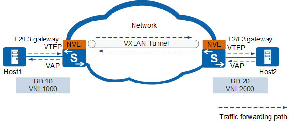
- One VTEP node can work as a VXLAN Layer 2 or 3 gateway, enabling flexible deployment.
- Unlike the centralized Layer 3 gateway which has to learn the ARP entries of all servers, the VTEP node only needs to learn the ARP entries of the connected server, solving the ARP entry problem of the centralized Layer 3 gateway and improving network scalability.
Comparison Between VXLAN and VLAN
The following table lists the differences between VXLAN and VLAN.
| Item | VLAN | VXLAN |
|---|---|---|
Concept |
Virtual local area network |
Virtual extensible local area network |
Implementation Method |
A physical LAN is divided into multiple BDs logically to limit the network to a small geographic range. |
Layer 2 virtual networks are established between networks with reachable routes. Such networks are not subject to geographical restrictions and can deliver a large-scale scalability. |
Supported capacity |
VLAN is the most commonly used network isolation technology. The VLAN field in packets is only 12 bits in length, which means that only a maximum of 4096 VLANs can be used on a network. In public cloud or other cloud computing scenarios involving tens of thousands or even more tenants, VLAN technology can no longer meet network isolation requirements. |
VXLAN is a new network isolation technology defined in IETF RFC 7348. It has a 24-bit segment identifier (VNI) and can isolate up to 16 million tenants. This technology effectively enables isolation of mass tenants in cloud computing. |
Network division mode |
VLAN IDs are used to divide broadcast domains. Hosts within a BD can communicate at Layer 2. |
BDs are used to divide broadcast domains. VMs within a BD can communicate at Layer 2. |
Encapsulation mode |
A VLAN tag is added to packets. |
During VXLAN encapsulation, a VXLAN header, UDP header, IP header, and outer MAC header are added in sequence to an original packet. For details, see Packet Encapsulation Format. |
Network communication mode |
Inter-VLAN communication is implemented by VLANIF interfaces. As Layer 3 logical interfaces, VLANIF interfaces enable Layer 3 communication between VLANs. |
Communication between VXLANs or between VXLANs and non-VXLANs is implemented by VBDIF interfaces. VBDIF interfaces are configured on VXLAN Layer 3 gateways and are Layer 3 logical interfaces based on BDs. |
Benefits |
Limits broadcast domains: A broadcast domain is limited in a VLAN, which saves bandwidth and improves network processing capabilities. Enhances LAN security: Packets from different VLANs are separately transmitted. Hosts in a VLAN cannot directly communicate with hosts in another VLAN. |
Location-independent capability: Services can be deployed flexibly at any location, solving network expansion issues related to server virtualization. Flexible network deployment: VXLANs are constructed over the traditional network. They are easy to deploy and highly scalable while preventing broadcast storms on a large Layer 2 network. Cloud service adaptation: A VXLAN is able to isolate ten millions of tenants and support large-scale deployment of cloud services. Technical advantage: VXLAN uses MAC-in-UDP encapsulation. Such encapsulation mode does not rely on MAC addresses of VMs, reducing the number of MAC address entries required on a large Layer 2 network. |