Distributed VXLAN Gateway Deployment Using BGP EVPN
In distributed VXLAN gateway deployment using BGP EVPN, the control plane is responsible for VXLAN tunnel establishment and dynamic MAC address learning; the forwarding plane is responsible for intra-subnet known unicast packet forwarding, intra-subnet BUM packet forwarding, and inter-subnet packet forwarding. This mode supports IP route advertisement, MAC address advertisement, and ARP advertisement, and ARP broadcast suppression can be directly enabled. For details on the functions, see BGP EVPN Basic Principles.
Combination Category |
Implementation Difference |
|---|---|
IPv6 over IPv4 |
|
IPv4 over IPv6 |
Not supported |
IPv6 over IPv6 |
Not supported |
VXLAN Tunnel Establishment
A VXLAN tunnel is identified by a pair of VTEP IP addresses. During VXLAN tunnel establishment, the local and remote VTEPs attempt to obtain the IP addresses of each other. A VXLAN tunnel can be established if the IP addresses obtained are reachable at Layer 3. When BGP EVPN is used to dynamically establish a VXLAN tunnel, the local and remote VTEPs first establish a BGP EVPN peer relationship and then exchange BGP EVPN routes to transmit VNIs and VTEPs' IP addresses.
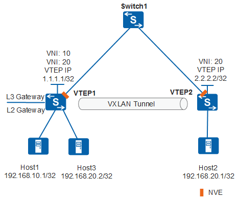
In distributed VXLAN gateway scenarios, VTEP nodes function as both Layer 2 and Layer 3 VXLAN gateways. Switch 1 is unaware of the VXLAN tunnels and only forwards VXLAN packets between different VTEP 1 and VTEP 2. On the network shown in Figure 1, a VXLAN tunnel is established between VTEP 1 and VTEP 2 for Host 1 and Host 2 or Host 3 and Host 2 to communicate. Host 1 and Host 3 both connect to VTEP 1, and therefore communication between Host 1 and Host 3 is allowed through VTEP 1, but not the VXLAN tunnel.
In distributed VXLAN gateway scenarios, VXLAN tunnels can be dynamically established using BGP EVPN for intra-subnet and inter-subnet communication.
Intra-subnet communication
On the network shown in Figure 2, intra-subnet communication between Host 2 and Host 3 requires only Layer 2 forwarding. The process for establishing a VXLAN tunnel using BGP EVPN is as follows:
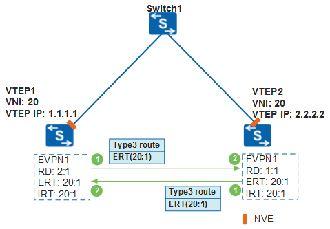
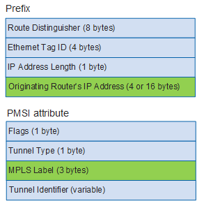
VTEP 1 and VTEP 2 establish a BGP EVPN peer relationship. Then, local EVPN instances are created on VTEP 2 and VTEP 3, and an RD, export VPN targets (ERT), and import VPN targets (IRT) are configured for the EVPN instance. Layer 2 broadcast domains are created and bound to VNIs and EVPN instances. After the local VTEP's IP address is configured on VTEP 1 and VTEP 2, they generate a BGP EVPN route and send it to each other. The BGP EVPN route carries the local EVPN instance's export VPN target and an inclusive multicast route (Type 3 route defined in BGP EVPN). Figure 3 shows the format of an inclusive multicast route, which comprises a prefix and a PMSI attribute. VTEP IP addresses are stored in the Originating Router's IP Address field in the inclusive multicast route prefix, and Layer 2 VNIs are stored in the MPLS Label field in the PMSI attribute.
After VTEP 1 and VTEP 2 receive a BGP EVPN route from each other, they match the export VPN targets of the route against the import VPN targets of the local EVPN instance. If a match is found, the route is accepted. If no match is found, the route is discarded. If the route is accepted, VTEP 1/VTEP 2 obtains the remote VTEP's IP address and Layer 2 VNI carried in the route. If the remote VTEP's IP address is reachable at Layer 3, a VXLAN tunnel to the remote VTEP is established. If the remote Layer 2 VNI is the same as the local Layer 2 VNI, an ingress replication list is created for subsequent BUM (Broadcast&Unknown-unicast&Multicast) packet forwarding.

A VPN target is an extended community attribute of BGP. An EVPN instance can have import and export VPN targets configured. The local EVPN instance's export VPN target must match the remote EVPN instance's import VPN target for EVPN route advertisement. If not, VXLAN tunnels cannot be dynamically established. If only one end can successfully accept the BGP EVPN route, this end can establish a VXLAN tunnel to the other end, but cannot exchange data packets with the other end. The other end drops packets after confirming that there is no VXLAN tunnel to the end that has sent these packets.
For details on VPN targets, see Basic Concepts of BGP/MPLS IP VPN in "BGP/MPLS IP VPN Configuration" in the S2720, S5700, and S6700V200R019C10 Configuration Guide - VPN.
Inter-subnet communication
Inter-subnet communication between Host 1 and Host 2 requires Layer 3 forwarding. When VXLAN tunnels are established using BGP EVPN, VTEP 1 and VTEP 2 must advertise the host IP routes. Generally, 32-bit host IP routes are advertised. Because different leaf nodes may connect to the same network segment on VXLANs, the network segment routes advertised by these leaf nodes may conflict. This conflict may cause host unreachability of some leaf nodes. Leaf nodes can advertise network segment routes in the following scenarios:
The network segment that a leaf node connects is unique on a VXLAN, and a large number of specific host routes are available. In this case, the network segment routes to which the host IP routes belong can be advertised so that leaf nodes do not have to store all these routes.
When hosts on a VXLAN need to access external networks, leaf nodes can advertise routes destined for external networks onto the VXLAN to allow other leaf nodes to learn the routes.
Before establishing a VXLAN tunnel, perform the following configurations on VTEP 1 and VTEP 2.
Configuration Task |
Function |
|---|---|
Create a Layer 2 BD and associate a Layer 2 VNI to the Layer 2 BD. |
A BD functions as a VXLAN network entity to transmit VXLAN data packets. |
Establish a BGP EVPN peer relationship between VTEP 1 and VTEP 2. |
This configuration is used to exchange BGP EVPN routes. |
Configure an EVPN instance and bound to a Layer 2 BD, and configure an RD, export VPN target (ERT), and import VPN target (IRT) for the EVPN instance. |
This configuration is used to generate BGP EVPN routes. |
Configure L3VPN instances for tenants and bind the L3VPN instances to the VBDIF interfaces of the Layer 2 BD. |
This configuration is used to differentiate and isolate IP routing tables of different tenants. |
Specify a Layer 3 VNI for an L3VPN instance. |
This configuration allows the leaf nodes to determine the L3VPN routing table for forwarding data packets. |
Configure export VPN targets (eERT) from an L3VPN instance to an EVPN instance and import VPN targets (eIRT) from an EVPN instance to an L3VPN instance. |
This configuration controls advertisement and reception of BGP EVPN routes between the local L3VPN instance and remote EVPN instance. |
Configure the type of route to be advertised between VTEP 1 and VTEP 2. |
This configuration is used to advertise IP routes between Host 1 and Host 2. Two types of routes are available, IRB and IP prefix routes, which can be selected as needed.
|
Dynamic VXLAN tunnel establishment varies depending on how host IP routes are advertised.
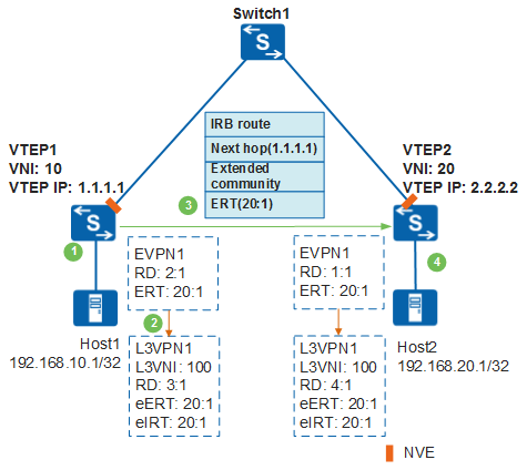
Host IP routes are advertised through IRB routes. (Figure 4 shows the process.)
When Host 1 communicates with VTEP 1 for the first time, VTEP 1 learns the ARP entry of Host 1 after receiving dynamic ARP packets. VTEP 1 then finds the L3VPN instance bound to the VBDIF interface of the Layer 2 BD where Host 1 resides, and obtains the Layer 3 VNI associated with the L3VPN instance. The EVPN instance of VTEP 1 then generates an IRB route based on the information obtained. Figure 5 shows the IRB route. The host IP address is stored in the IP Address Length and IP Address fields; the Layer 3 VNI is stored in the MPLS Label2 field.
The EVPN instance of VTEP 1 obtains Host 1's IP address and Layer 3 VNI from the IRB route and sends it to the local L3VPN instance. The L3VPN instance then stores Host 1's IP route in the routing table. Figure 6 shows the host IP route.
VTEP 1 generates and sends a BGP EVPN route to VTEP 2. The BGP EVPN route carries the local EVPN instance's export VPN targets (ERT), extended community attribute, Next_Hop attribute, and the IRB route. The extended community attribute carries the tunnel type (VXLAN tunnel) and local VTEP MAC address; the Next_Hop attribute carries the local VTEP IP address.
After VTEP 2 receives the BGP EVPN route from VTEP 1, VTEP 2 processes the route as follows:
Matches the ERT of the route against the import VPN targets (IRT) of the local EVPN instance. If a match is found, the route is accepted. After the EVPN instance obtains IRB routes, it can extract ARP routes from the IRB routes to implement ARP advertisement.
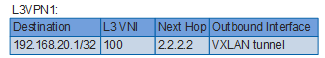
Matches the ERT of the route against the import VPN targets (eIRT) of the local L3VPN instance. If a match is found, the route is accepted. The L3VPN instance obtains the IRB route, extracts Host 1's IP address and Layer 3 VNI, stores Host 1's IP route in the routing table. Based on the next hop, the IP route's outbound interface is iterated to the VXLAN tunnel destined for Leaf1. Figure 7 shows the host route.
Only when the ERT in a BGP EVPN route is different from the local EVPN instance's IRT and local L3VPN instance's eIRT, the route is discarded.
If the route is accepted by the EVPN instance or L3VPN instance, VTEP 2 obtains VTEP 1's VTEP IP address from the Next_Hop attribute. If the VTEP IP address is reachable at Layer 3, a VXLAN tunnel to VTEP 1 is established.
VTEP 1 establishes a VXLAN tunnel to VTEP 2 in the same process.
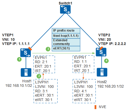
Host IP routes are advertised through IP prefix routes. Figure 8 shows the process.
VTEP 1 generates a direct route to Host 1's IP address. Then, VTEP 1 has an L3VPN instance configured to import the direct route, so that Host 1's IP route is saved to the routing table of the L3VPN instance and the Layer 3 VNI associated with the L3VPN instance is added. Figure 9 shows the host IP route.
If network segment route advertisement is required, use a dynamic routing protocol, such as OSPF. Then, configure an L3VPN instance to import the routes of the dynamic routing protocol.
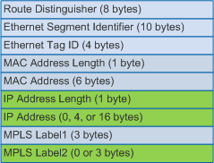
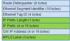
If VTEP 1 is configured to advertise IP routes in the L3VPN instance to the EVPN instance, VTEP 1 advertise Host 1's IP routes in the L3VPN instance to the EVPN instance. The EVPN instance then generates IP prefix routes. Figure 10 shows the IP prefix route. The host IP address is stored in the IP Prefix Length and IP Prefix fields; the Layer 3 VNI is stored in the MPLS Label field.
VTEP 1 generates and sends a BGP EVPN route to VTEP 2. The BGP EVPN route carries the local L3VPN instance's export VPN targets (eERT), extended community attribute, Next_Hop attribute, and the IP prefix route. The extended community attribute carries the tunnel type (VXLAN tunnel) and local VTEP MAC address; the Next_Hop attribute carries the local VTEP IP address.
After VTEP 2 receives the BGP EVPN route from VTEP 1, VTEP 2 processes the route as follows:
Matches the eERT of the route against the import VPN targets (eIRT) of the local L3VPN instance. If a match is found, the route is accepted. If no match is found, the route is discarded. The L3VPN instance obtains the IP prefix route, extracts Host 1's IP address and Layer 3 VNI, stores Host 1's IP route in the routing table, and sets the next hop's iterated outbound interface to the VXLAN tunnel interface. Figure 11 shows the host route.
If the route is accepted by the L3VPN instance, VTEP 2 obtains VTEP 1's VTEP IP address from the Next_Hop attribute. If the VTEP IP address is reachable at Layer 3, a VXLAN tunnel to VTEP 1 is established.
VTEP 1 establishes a VXLAN tunnel to VTEP 2 in the same process.
Dynamic MAC Address Learning
VXLAN supports dynamic MAC address learning to allow communication between tenants. MAC address entries are dynamically created and do not need to be manually maintained, greatly reducing maintenance workload. In distributed VXLAN gateway scenarios, inter-subnet communication requires Layer 3 forwarding; MAC address learning is implemented using ARP between the local host and gateway. The following example illustrates dynamic MAC address learning for intra-subnet communication on the network shown in Figure 12.
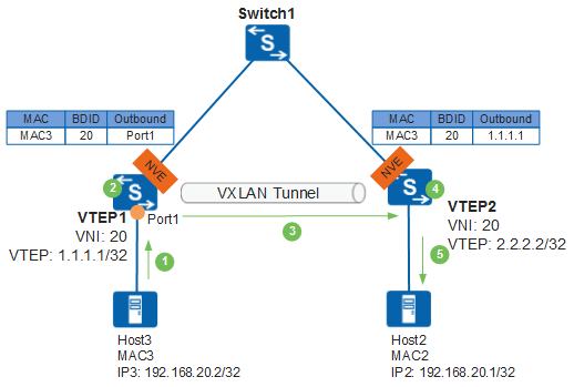
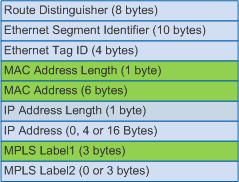
When Host 3 communicates with VTEP 1 for the first time, VTEP 1 learns the mapping between Host 3's MAC address, BDID (Layer 2 broadcast domain ID), and inbound interface (Port1) that has received the dynamic ARP packet and generates a MAC address entry for Host 3. The MAC address entry's outbound interface is Port1. VTEP 1 generates and sends a BGP EVPN route based on the ARP entry of Host 3 to VTEP 2. The BGP EVPN route carries the local EVPN instance's export VPN targets, Next_Hop attribute, and a Type 2 route (MAC/IP route) defined in BGP EVPN. The Next_Hop attribute carries the local VTEP's IP address. The MAC Address Length and MAC Address fields identify Host 3's MAC address. The Layer 2 VNI is stored in the MPLS Label1 field. Figure 13 shows the format of a MAC/IP route.
After VTEP 2 receives a BGP EVPN route from VTEP 1, VTEP 2 matches the export VPN targets of the route against the import VPN targets of the local EVPN instance. If a match is found, the route is accepted. If no match is found, the route is discarded. If the route is accepted, VTEP 2 obtains the mapping between Host 3's MAC address, BDID, VTEP 1's VTEP IP address (Next_Hop attribute) and generates a MAC address entry for Host 3. Based on the next hop, the MAC address entry's outbound interface is iterated to the VXLAN tunnel destined for VTEP 1.
VTEP 1 learns the MAC route of Host 2 in the same process.
When Host 3 communicates with Host 2 for the first time, Host 3 sends an ARP request for Host 2's MAC address. The ARP request carries the destination MAC address being all Fs and destination IP address being IP2. By default, VTEP 1 broadcasts the ARP request onto the network segment after receiving it. To reduce broadcast packets, ARP broadcast suppression can be enabled on VTEP 1. In the case ARP broadcast suppression is enabled and VTEP 1 receives the ARP request, VTEP 1 checks whether it has Host 2's MAC address based on the destination IP address of the ARP request. If VTEP 1 has Host 2's MAC address, it replaces the destination MAC address of the ARP request with Host 2's MAC address and unicasts the ARP request to VTEP 2 through the VXLAN tunnel. Upon receipt, VTEP 2 forwards the ARP request to Host 2, which then learns Host 3's MAC address and responds with an ARP reply in unicast mode. After Host 3 receives the ARP reply, it learns Host 2's MAC address. So far, Host 2 and Host 3 have learned the MAC address of each other, and will subsequently communicate with each other in unicast mode.
Leaf nodes can learn the MAC addresses of hosts during data forwarding, if this capability is enabled. If VXLAN tunnels are established using BGP EVPN, leaf nodes can dynamically learn the MAC addresses of hosts through BGP EVPN routes, rather than data forwarding.
Intra-Subnet Known Unicast Packet Forwarding
Intra-subnet known unicast packets are forwarded only through Layer 2 VXLAN gateways and are unknown to Layer 3 VXLAN gateways. Figure 14 shows the intra-subnet known unicast packet forwarding process.
- After VTEP 1 receives Host 3's packet, it determines the Layer 2 BD of the packet based on the access interface and VLAN information and searches for the outbound interface and encapsulation information in the BD.
- VTEP 1 performs VXLAN encapsulation based on the encapsulation information obtained and forwards the packets through the outbound interface obtained.
- Upon receipt of the VXLAN packet, VTEP 2 verifies the VXLAN packet based on the UDP destination port number, source and destination IP addresses, and VNI. VTEP 2 obtains the Layer 2 BD based on the VNI and performs VXLAN decapsulation to obtain the inner Layer 2 packet.
- VTEP 2 obtains the destination MAC address of the inner Layer 2 packet, performs VLAN tags to the packets based on the outbound interface and encapsulation information in the local MAC address table, and forwards the packets to Host 2.
Host 2 sends packets to Host 3 in the same process.
Intra-Subnet BUM Packet Forwarding
Intra-subnet BUM packet forwarding is completed between Layer 2 VXLAN gateways. Layer 3 VXLAN gateways do not need to be unaware of the process. Intra-subnet BUM packets can be forwarded in ingress replication mode.
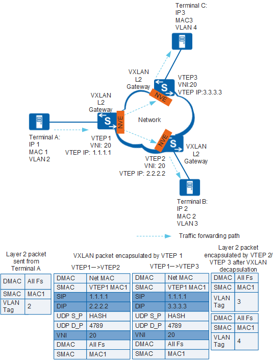
- After VTEP 1 receives Terminal A's packet, it determines the Layer 2 BD of the packet based on the access interface and VLAN information.
- VTEP 1 obtains the ingress replication list for the VNI, replicates packets based on the list, and performs VXLAN encapsulation by adding outer headers. VTEP 1 then forwards the VXLAN packet through the outbound interface.
- Upon receipt of the VXLAN packet, VTEP 2 and VTEP 3 verify the VXLAN packet based on the UDP destination port number, source and destination IP addresses, and VNI. VTEP 2/VTEP 3 obtains the Layer 2 BD based on the VNI and performs VXLAN decapsulation to obtain the inner Layer 2 packet.
- VTEP 2/VTEP 3 checks the destination MAC address of the inner Layer 2 packet and finds it a BUM MAC address. Therefore, VTEP 2/VTEP 3 broadcasts the packet onto the network connected to the terminals (not the VXLAN tunnel side) in the Layer 2 broadcast domain. Specifically, VTEP 2/VTEP 3 finds the outbound interfaces and encapsulation information not related to the VXLAN tunnel, performs VLAN tags to the packet, and forwards the packet to Terminal B/Terminal C.
Terminal B/Terminal C responds to Terminal A in the same process as intra-subnet known unicast packet forwarding.
Inter-Subnet Packet Forwarding
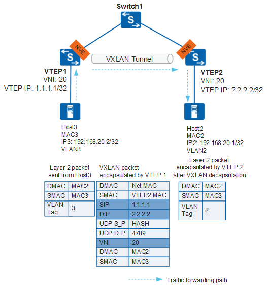
Inter-subnet packets must be forwarded through a Layer 3 gateway. Figure 16 shows the inter-subnet packet forwarding process in distributed VXLAN gateway scenarios.
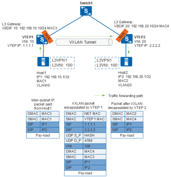
- After VTEP 1 receives a packet from Host 1, it finds that the destination MAC address of the packet is a gateway MAC address so that the packet must be forwarded at Layer 3.
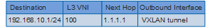
- VTEP 1 determines the Layer 2 broadcast domain of the packet based on the inbound interface and accordingly finds the L3VPN instance bound to the VBDIF interface of the Layer 2 broadcast domain. VTEP 1 then searches the L3VPN routing table and finds the destination address of packet. Figure 17 shows the host route in the L3VPN routing table. VTEP 1 obtains the Layer 3 VNI and next hop address of the host route and find that the iterated outbound interface is a VXLAN tunnel interface. Therefore, VTEP 1 determines that the packet must be transmitted through a VXLAN tunnel. Because the packet must be transmitted over a VXLAN tunnel, VTEP 1 performs VXLAN encapsulation as follows:
- Obtains the MAC address based on the VXLAN tunnel's source and destination IP addresses and replace the source and destination MAC addresses in the inner Ethernet header.
- Encapsulates the packet with the Layer 3 VNI.
- Encapsulates the VXLAN tunnels' source and destination IP addresses in the outer IP header, and VTEP 1's MAC address as the source MAC address and MAC address of the next hop pointing to the destination IP address as the destination MAC address in the outer Ethernet header.
- The VXLAN packet is then transmitted over the IP network based on the IP and MAC addresses in the outer headers and finally reaches VTEP 2.
- After VTEP 2 receives the VXLAN packet, it decapsulates the packet and finds that the destination MAC address is its own MAC address so that the packet must be forwarded at Layer 3.
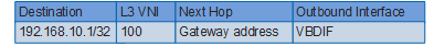
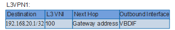
- VTEP 2 determines the L3VPN instance bound to the Layer 3 VNI of the packet, searches the L3VPN routing table, and finds the next hop being the gateway IP address. VTEP 2 replaces the destination MAC address with Host 2's MAC address (MAC2) and source MAC address with VTEP 2's MAC address and sends the packet to Host 2. Figure 18 shows the host route in the L3VPN routing table.
Host 2 sends packets to Host 1 in the same process.
When a Huawei device communicates with a non-Huawei device, ensure that the non-Huawei device uses the same forwarding mode as that of the Huawei device. If they use different forwarding modes, the communication may fail.