Port Numbering Conventions
Physical ports are numbered in the following way:
- Slot ID: indicates the slot where the switch is located. The value is 0.
- Subcard ID: indicates the ID of a subcard.
- Port sequence number: indicates the sequence number of a port on the switch.
- Stack ID: indicates the ID of a stacked switch. The value ranges from 0 to 8.
- Subcard ID: indicates the ID of a subcard.
- Port sequence number: indicates the sequence number of a port on the switch.
Port Numbering Diagram |
Description |
|---|---|
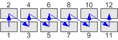 |
There are two rows of service ports on the device. These ports are numbered from bottom to top and left to right, starting from 1. For example, the port on the top left is numbered 0/0/2. Ports of different speeds are numbered separately. For example, the first 100M port is numbered ethernet 0/0/1, and the first GE port is numbered gigabitethernet 0/0/1. Other 100M and GE ports are numbered in ascending order following the two ports respectively. |
Table 2 describes the CSFP port numbering conventions.
Port Numbering Diagram |
Description |
|---|---|
|
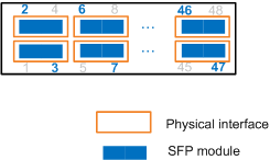
For example, an S5700-52X-LI-48CS-AC has 24 physical ports
located in two rows of service ports, 12 ports in each row. When all
the ports have SFP optical modules installed, the ports are numbered
as follows:
For example, with SFP optical modules installed, the first port at the lower left of the panel is numbered 0/0/3; the second port at the lower left is numbered 0/0/7; the first port at the upper left is numbered 0/0/2; the second port at the upper left is numbered 0/0/6. |
|
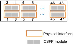
When all the ports have CSFP optical modules installed, each port functions as two ports. The switch has a total of 48 ports in this case. These ports are numbered starting with 1 from bottom to top, and left to right. For example, if a CSFP optical module is installed on the first port at the lower left, the port is split into two ports numbered 0/0/1 and 0/0/3. If a CSFP optical module is installed on the first port at the upper left, the port is split into two ports numbered 0/0/2 and 0/0/4. |
|
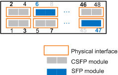
If some ports on the switch use CSFP optical modules and some use SFP optical modules, the ports are numbered following the perspective numbering conventions. Assume that the first port at the lower left uses a CSFP optical module and the second port at the upper left uses an SFP optical module. In this case, the two ports derived from the first CSFP port are numbered 0/0/1 and 0/0/3, and the second SFP port is numbered 0/0/6. |