Example for Configuring Interface-based VLANs
Networking Requirements
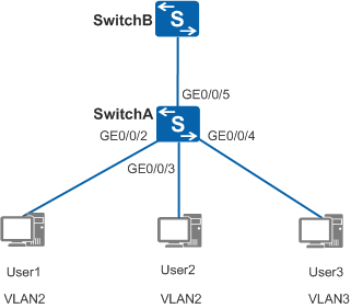
As shown in Figure 1, the switch of an enterprise
connects to many users, and users accessing the same service connect
to the enterprise network through different devices. To ensure communication
security and prevent broadcast storms, the enterprise allows only
the users accessing the same service to communicate with each other.
You can assign and configure VLANs on the switch based on interfaces
so that the switch adds interfaces connected to users using the same
service to the same VLAN. Users in different VLANs cannot communicate
at Layer 2. Users in the same VLAN can directly communicate with each
other. That is:
- User 1 and user 2 in VLAN 2 are isolated from user 3 in VLAN 3.
- User 1 and user 2 in VLAN 2 can communicate with each other.
Configuration Roadmap
The configuration roadmap is as follows:
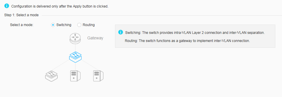
- Select the switching mode.
- Configure the port connected to terminals.
- Configure the port connected to the upstream gateway.
Procedure
- Choose . Select Switching for Select a mode to open the quick switching mode configuration page, as shown in Figure 2.
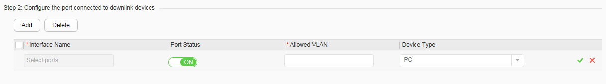
- Click Add below Step 2:
Configure the port connected to downlink devices, as shown
in Figure 3.
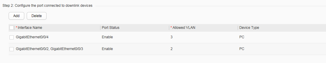
Set all configuration items as follows. Then click
 to finish the
configuration. Figure 4 displays the configuration
result.
to finish the
configuration. Figure 4 displays the configuration
result.Configure GE0/0/2 and GE0/0/3:
- Interface name: GigabitEthernet0/0/2, GigabitEthernet0/0/3
- Port status: ON
- Allowed VLAN: 2
- Device Type: PC
Configure GE0/0/4:
- Interface name: GigabitEthernet0/0/4
- Port status: ON
- Allowed VLAN: 3
- Device Type: PC
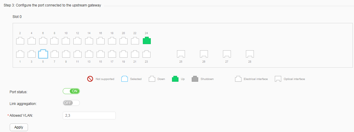
- Click GE0/0/5 below Step 3: Configure the port
connected to the upstream gateway, and set all configuration
items, as shown in Figure 5.
- Port status: ON
- Link aggregation: OFF
- Allowed VLAN: 2, 3
- Click Apply. In the dialog box that is displayed, click OK.