Example for Configuring VLANIF Interfaces to Implement Inter-VLAN Communication
Networking Requirements
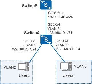
User hosts of an enterprise use the same services, and are located on different network segments. These user hosts belong to different VLANs and need to communicate with each other.
As shown in Figure 1, user 1 and user 2 using the same service
belong to different VLANs and different network segments. User 1 and
user 2 can communicate through a VLANIF interface.
Configuration Roadmap
The following configurations are performed on SwitchA. The configuration roadmap is as follows:
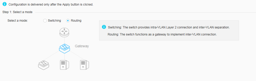
- Select the routing mode.
- Configure the port connected to terminals on internal network.
- Configure the port connected to the switch on external network.
Procedure
- Choose . Select Routing for Step 1: Select a mode to open the quick switching mode configuration page, as shown in Figure 2.
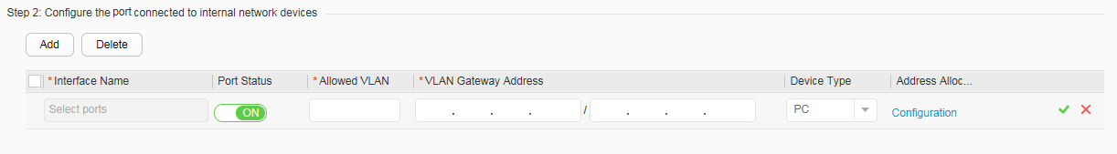
- Click Add below Step 2:
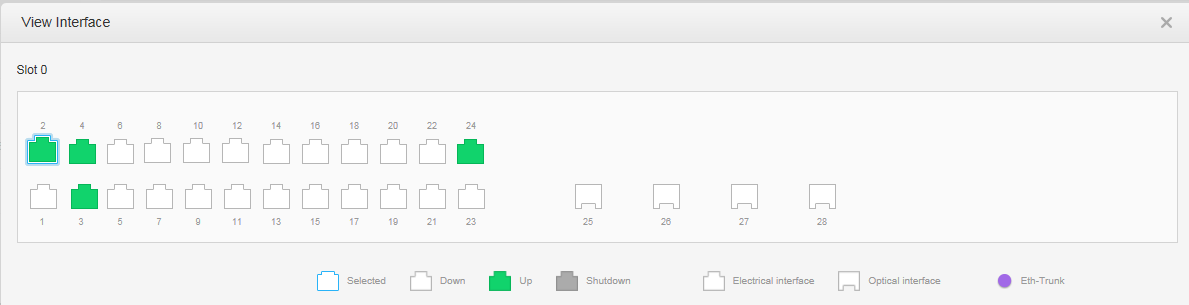
Configure the port connected to internal network devices, as shown in Figure 3.
Set all configuration items as follows. Then click
 to finish the
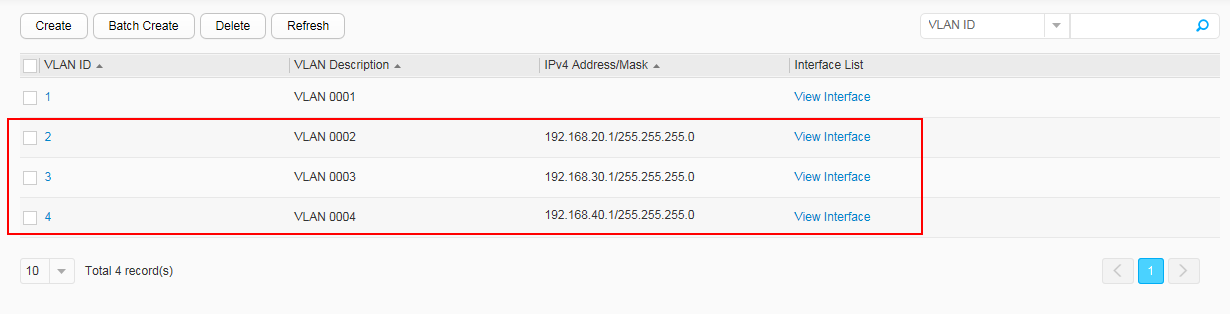
configuration. Figure 4 displays the configuration
result.
to finish the
configuration. Figure 4 displays the configuration
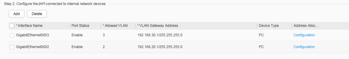
result.Configure GE0/0/2:
- Interface Name: GigabitEthernet0/0/2
- Port Status: ON
- Allowed VLAN: 2
- VLAN Gateway Address: 192.168.20.1/255.255.255.0
- Device Type: PC
- Address Allocation to Terminals: Click Configuration to choose static allocation.
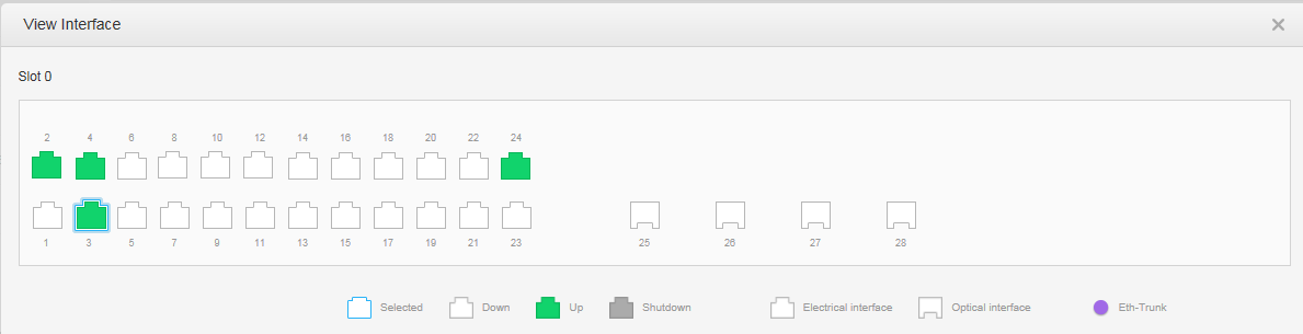
Configure GE0/0/3:
- Interface Name: GigabitEthernet0/0/3
- Port Status: ON
- Allowed VLAN: 3
- VLAN Gateway Address: 192.168.30.1/255.255.255.0
- Device Type: PC
- Address Allocation to Terminals: Click Configuration to choose static allocation.
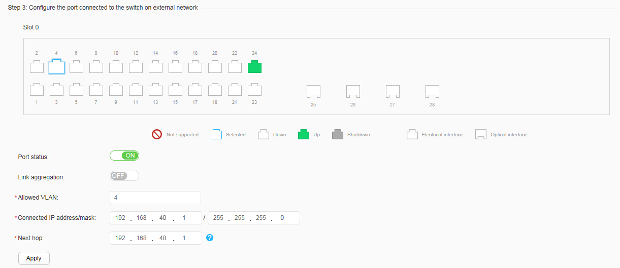
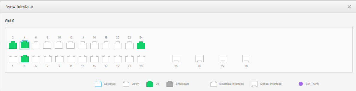
- Choose GE0/0/4 below Step 3: Configure the port
connected to the switch on external network. Set all configuration
items, as shown in Figure 5.
- Port Status: ON
- Link aggregation: OFF
- Allowed VLAN: 4
- Connected IP address/mask: 192.168.40.1/255.255.255.0
- Next hop: 192.168.40.4
- Click Apply. In the dialog box that
is displayed, click OK to finish configuration.

If router A is connected to public networks, you need to configure a NAT policy on router A to implement translation between public and private IP addresses.
You also need to configure a subinterface for the inbound interface of router A to remove tags from VLAN packets.