Example for Using Advanced ACLs to Restrict Mutual Access Between Network Segments
Networking Requirements
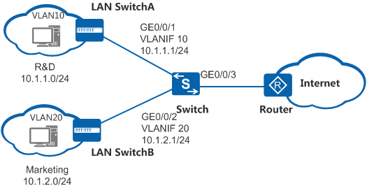
As shown in Figure 1, the departments of an enterprise are connected through a switch. To facilitate network management, the administrator allocates IP addresses of different network segments to the R&D and marketing departments. In addition, the administrator adds the two departments to different VLANs for broadcast domain isolation. For information security purposes, the enterprise requires that the switch prevent user hosts on different network segments from communicating with each other.
Configuration Roadmap
- Configure VLANs and configure IP addresses for VLANIF interfaces.
- Configure advanced ACLs.
- Apply the ACLs to enable the device to filter user packets based on the source and destination IP addresses, thereby restricting mutual access between users on different network segments.
Procedure
- Add interfaces to VLANs and assign IP addresses to the VLANIF interfaces.
- Click Create. The Create VLAN dialog box is displayed.
- Enter 10 in the VLAN ID text box.
- Select Create VLANIF, enter 10.1.1.1 in the IPv4 address text box, and set Mask to 24.
- Click Add Interface and then Select Interface, select GigabitEthernet0/0/1.
- Click OK, as shown in Figure 2.
- Click Create. The Create VLAN dialog box is displayed.
- Configure ACLs.
- Click Create. In the Create ACL dialog box, set ACL number to 3001 and click OK, as shown in Figure 3.
- Click Add Rule on the right of ACL 3001. In the Add Rule dialog box, set Action, Protocol type, Source IP, Destination IP and Wildcard, and click OK, as shown in Figure 4.
- Create and configure ACL 3002 in the same way based on Figure 5.
- Apply the ACLs.
- Set Interface name. Click New next to Inbound interface ACL number, and select ACLs, as shown in Figure 6 and Figure 7. Click Apply to apply the ACLs.

The traffic from the marketing department to the R&D department enters the switch through GE0/0/2, and the traffic from the R&D department to the marketing department enters the switch through GE0/0/1. Therefore, apply the corresponding ACL to the inbound direction on the two interfaces.
- Set Interface name. Click New next to Inbound interface ACL number, and select ACLs, as shown in Figure 6 and Figure 7. Click Apply to apply the ACLs.


