Example for Using Advanced ACLs to Control Access to the Specified Server in the Specified Time Range
ACL Overview
An Access Control List (ACL) consists of one rule or a set of rules that describe the packet matching conditions. These conditions include source addresses, destination addresses, and port numbers of packets.
An ACL filters packets based on rules. A device with an ACL configured matches packets based on the rules to obtain the packets of a certain type, and then decides to forward or discard these packets according to the policies used by the service module to which the ACL is applied.
Depending on the rule definition methods, ACLs include basic ACL, advanced ACL, and Layer 2 ACL. An advanced ACL defines rules to filter IPv4 packets based on source IP addresses, destination IP addresses, IP protocol types, TCP source/destination port numbers, UDP source/destination port numbers, fragment information, and time ranges. Compared with a basic ACL, an advanced ACL is more accurate, flexible, and provides more functions. For example, if you want to filter packets based on source and destination IP addresses, configure an advanced ACL.
In this example, an advanced ACL is configured so that the device can filter the packets sent from external hosts to internal servers and thus restrict access of external hosts to internal servers.
Networking Requirements
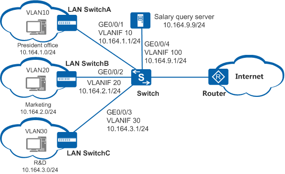
As shown in Figure 1, the departments of an enterprise are connected through the Switch. The R&D and marketing departments cannot access the salary query server at 10.164.9.9/24 in work hours (08:00 to 17:30), whereas the president office can access the server at anytime.
Configuration Roadmap
- Configure VLANs and configure IP addresses for VLANIF interfaces.
- Configure a time range and advanced ACLs.
- Apply the ACLs so that the device can filter packets sent from users to the server in the specified time range. In this way, you can restrict the access of different users to the server in the specified time range.
Procedure
- Add interfaces to VLANs and assign IP addresses to the VLANIF interfaces.
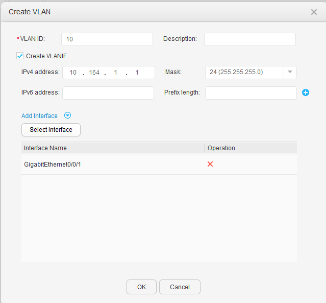
- Click Create. The Create VLAN dialog box is displayed.
- Enter 10 in the VLAN ID text box.
- Select Create VLANIF, enter 10.164.1.1 in the IPv4 address text box, and set Mask to 24.
- Click Add Interface and then Select Interface, select GigabitEthernet0/0/1, and click OK.
Click OK, as shown in Figure 2.
- Click Create. The Create VLAN dialog box is displayed.
- Configure a time range.
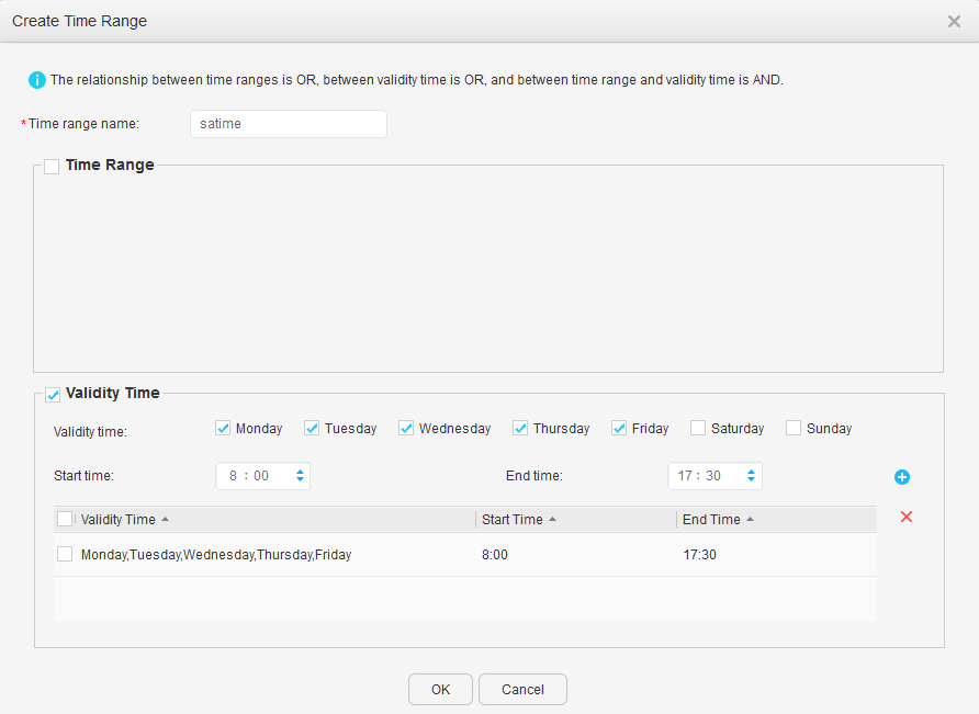
- Click Create. The Create Time Range dialog box is displayed.
- Set Time range name.
- Deselect Time Range.
- Select Validity Time, set Validity time, Start time, and End time, and click
 .
.
Click OK, as shown in Figure 3.
- Click Create. The Create Time Range dialog box is displayed.
- Configure ACLs.
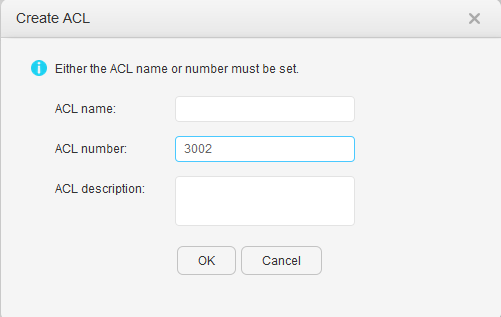
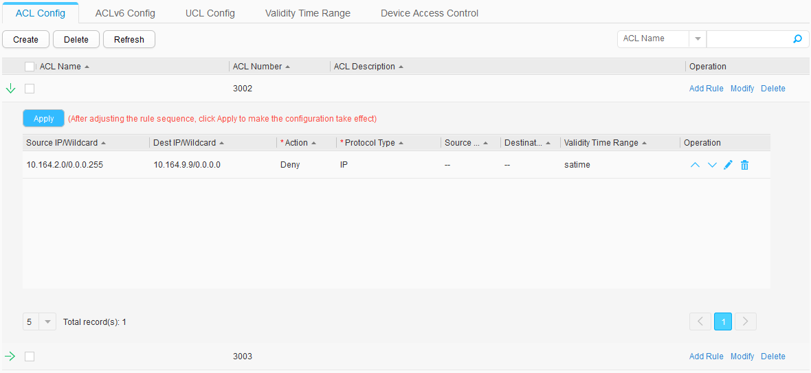
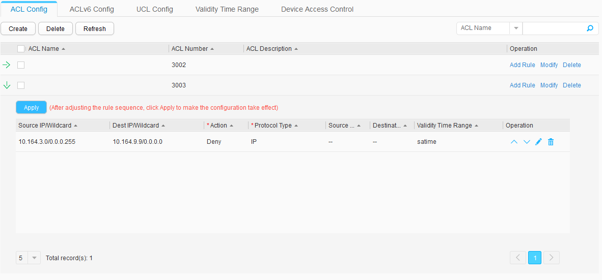
- Click Create. In the Create ACL dialog box, set ACL number to 3002 and click OK, as shown in Figure 4.
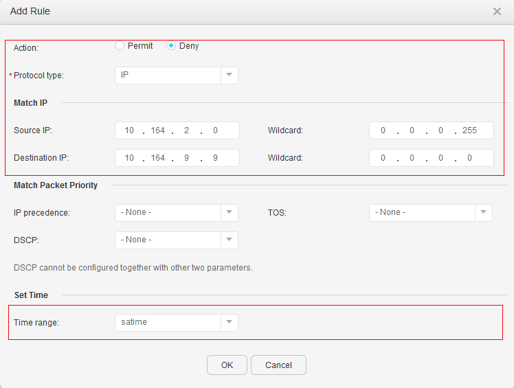
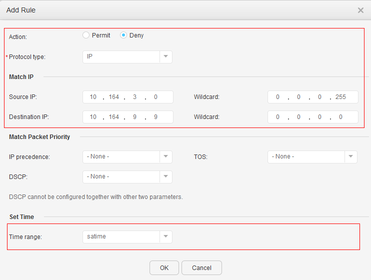
- Click Add Rule on the right of ACL 3002. In the Add Rule dialog box, set Action, Protocol type, Source IP, Destination IP, Wildcard, and Time range, and click OK, as shown in Figure 5.
- Create and configure ACL 3003 in the same way based on Figure 6.
- Apply the ACLs.
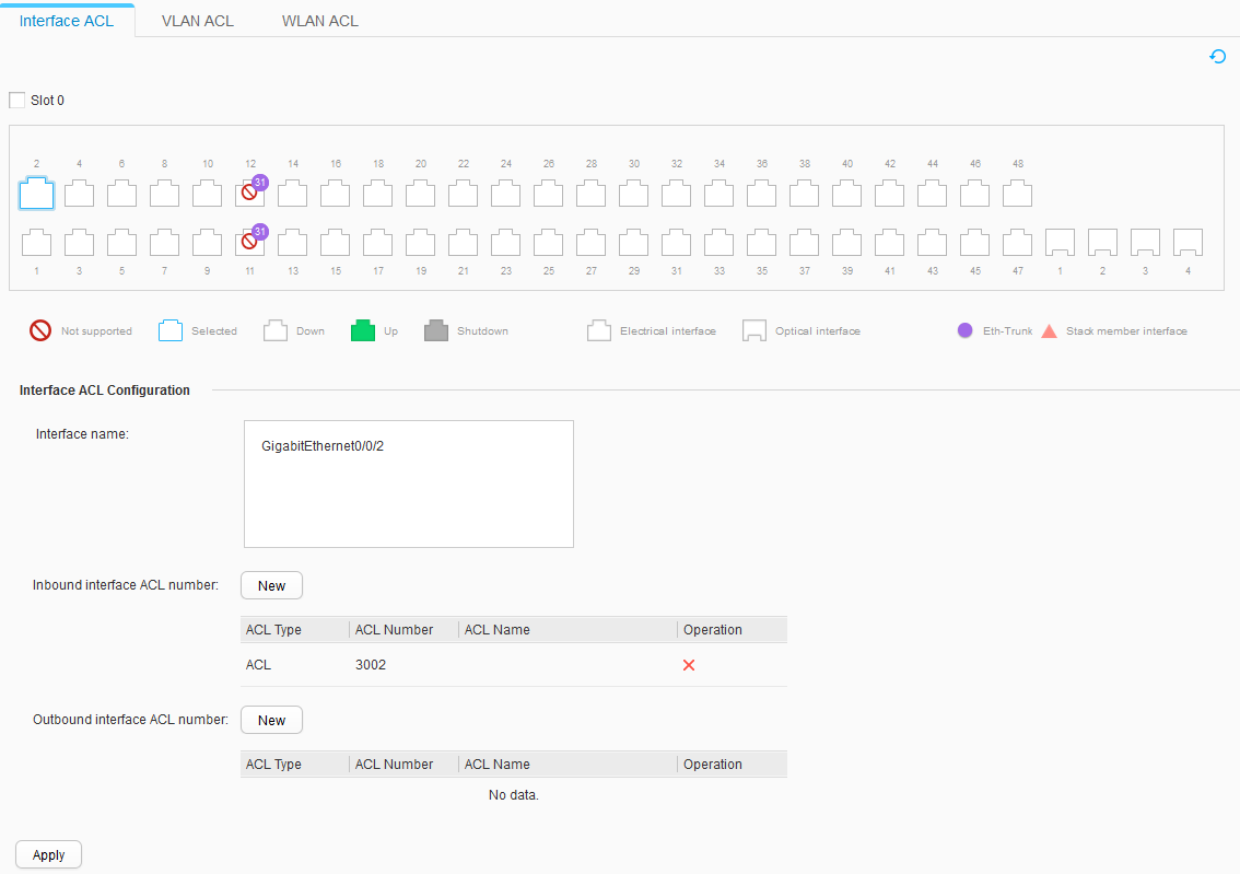
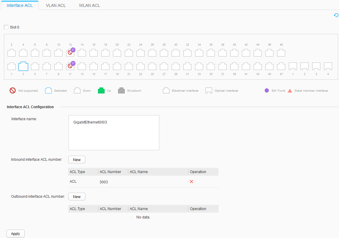
- Set Interface name. Click New next to Inbound interface ACL number, and select ACLs, as shown in Figure 7 and Figure 8. Click Apply to apply the ACLs.
 The inbound interface of traffic from the marketing department to the server is GE0/0/2 of Switch. The inbound interface of traffic from the R&D department to the server is GE0/0/3 of Switch. Therefore, apply ACLs on the two inbound interfaces, respectively.
- Set Interface name. Click New next to Inbound interface ACL number, and select ACLs, as shown in Figure 7 and Figure 8. Click Apply to apply the ACLs.