Example for Configuring a Small-Sized Campus Network
Networking Requirements
In an enterprise, intranet users in departments A and B can communicate with each other and access the Internet.
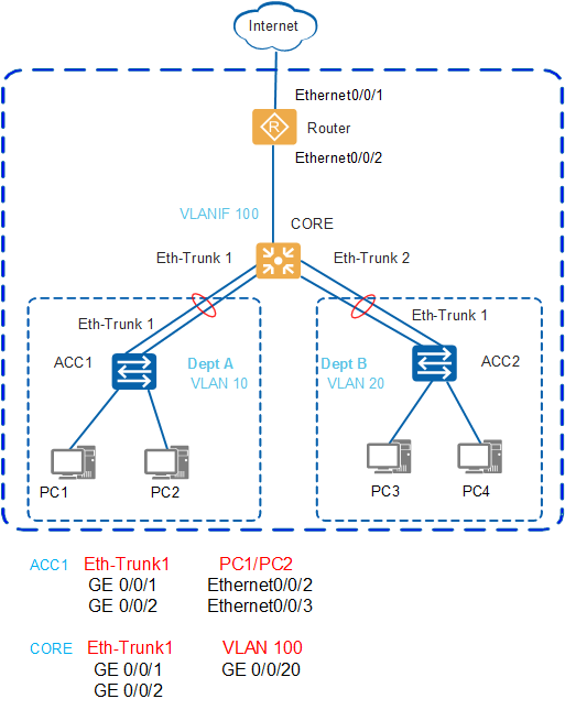
As shown in Figure 1, on a small-sized campus network, S2700 switches are typically deployed as access switches (such as ACC1) at the access layer, S6700 switches as core switches (such as CORE) at the core layer, and AR routers as egress routers (such as Router).
The access switches are connected to the core switch through Eth-Trunks to ensure reliability.
A VLAN is assigned to each department and services are transmitted between departments at Layer 3 through VLANIF interfaces of the switch CORE.
The core switch functions as a DHCP server to allocate IP addresses to users in the campus.
The DHCP snooping function is configured on access switches to prevent intranet users from connecting to unauthorized routers to obtain IP addresses. The IPSG function is configured to prevent intranet users from changing their IP addresses.
Data Planning
Operation |
Item |
Data |
Description |
|---|---|---|---|
Configuring the management IP address |
IP address of the management interface |
10.10.1.1/24 |
This IP address is used for users to log in to the switch through the management interface. |
Configuring interfaces and VLANs |
Eth-Trunk working mode |
Static Link Aggregation Control Protocol (LACP) mode |
Eth-Trunks work in manual load balancing mode or static LACP mode. |
Interface type |
Interfaces connected to switches are configured as trunk interfaces and interfaces connected to PCs are configured as access interfaces. |
A trunk interface is typically used to connect to a switch. An access interface is typically used to connect to a PC. A hybrid interface can connect to either a switch or a PC. |
|
VLAN ID |
ACC1: VLAN 10 ACC2: VLAN 20 CORE: VLANs 100, 10, and 20 |
The default VLAN of a switch is VLAN 1. To isolate departments A and B at Layer 2, add department A to VLAN 10 and department B to VLAN 20. The switch CORE connects to the egress router through VLANIF 100. |
|
Configuring DHCP |
DHCP server |
CORE |
The DHCP server is deployed on the core switch. |
Address pool |
VLAN 10: VLANIF 10 VLAN 20: VLANIF 20 |
Terminals in department A obtain IP addresses from the address pool on VLANIF 10. Terminals in department B obtain IP addresses from the address pool on VLANIF 20. |
|
Configuring routes on the core switch |
IP routes |
VLANIF 100: 10.10.100.1/24 VLANIF 10: 10.10.10.1/24 VLANIF 20: 10.10.20.1/24 |
The IP address of VLANIF 100 is used for the switch CORE to connect to the egress router and for the internal network to communicate with the Internet. On the core switch, configure a default route and set the next-hop IP address to the IP address of the egress router. After the IP addresses of VLANIF 10 and VLANIF 20 are configured on the switch CORE, departments A and B can communicate through the switch. |
Configuring the egress router |
IP address of the public network interface |
Ethernet0/0/1: 1.1.1.2/30 |
Ethernet0/0/1 connects the egress router to the Internet. |
IP address of the public network gateway |
1.1.1.1/30 |
It is the IP address of the carrier's device connected to the egress router. On the egress router, configure a default route to this IP address for forwarding network traffic to the Internet. |
|
DNS server address |
2.2.2.2 |
The DNS server resolves a domain name into an IP address. |
|
IP address of an intranet interface |
Ethernet0/0/2: 10.10.100.2/24 |
Ethernet0/0/2 connects the egress router to the intranet. |
|
Configuring DHCP snooping and IPSG |
Trusted port |
Eth-Trunk 1 |
N/A |
Configuration Roadmap
The configuration roadmap is as follows:
- Log in to switches.
- Configure the interfaces and VLANs on access switches.
- Configure the interfaces and VLAN on the core switch.
- Configure the DHCP server on the core switch.
- Configure routes on the core switch.
- Configure the egress router.
- Configure DHCP snooping and IPSG on access switches.
- Save the configuration.
Procedure
- Log in to a switch.

A switch using factory settings can be logged in to through the web system for the first time. The following uses the switch CORE as an example to describe how to log in to a switch through the web system for the first time. The login methods of switches ACC1 and ACC2 are similar to that of the switch CORE.
The switch that does not have the MODE button and does not use factory settings cannot be logged in to through the web system for the first time. However, subsequent logins through the web system are supported. For details, see Web System Login.
- Log in to the switch through the web system.
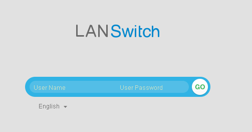
Open a browser on the PC, enter https://192.168.1.253 in the address box, and press Enter. The web system login page is displayed, as shown in Figure 2. Enter the default user name admin and password admin@huawei.com, and select the system language. Click GO or press Enter. The web system configuration page is displayed.
To log in to a switch through the web system for the first time, you must use Microsoft Edge, Internet Explorer 10.0, Internet Explorer 11.0, Firefox61.0 to Firefox66.0, and Google Chrome 64.0 to 73.0. If a browser or browser patch is not in the specified range, the web page may not be properly displayed. Upgrade the browser and browser patch.
- Configure the switch.On the web configuration page, perform the following operations in the Basic Setting area:
- Set Management IP Address to 10.10.1.1 and Mask to 24(255.255.255.0).
- Enter admin@huawei.com in the Old Password text box.
- Enter a new password in WEB User Password and Confirm Password text boxes.
- Select 15 from the WEB User Level drop-down list box.
The configured management IP address and 192.168.1.253/24 are not on the same network segment, so you cannot log in to the switch through the web system after exiting the first login page. Therefore, the IP address of the PC needs to be configured again to ensure that the switch and PC are reachable.
- Log in to the switch through the web system.
- Configure interfaces and VLANs on access switches (ACC1 is used as an example here, and the configuration on ACC2 is similar).
- Configure Eth-Trunk 1 that connects ACC1 to CORE to transparently transmit packets from the VLAN of department A.
- Choose , and click Connect to Switch in the Select Task area.
- Select GigabitEthernet0/0/1 and GigabitEthernet0/0/2 to be configured.
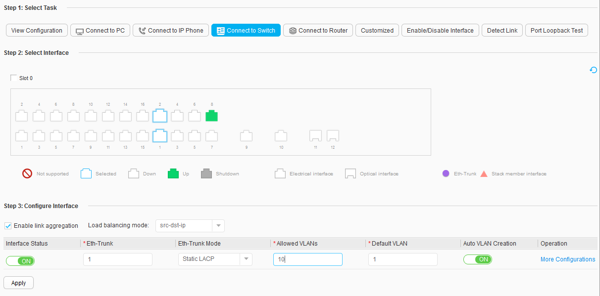
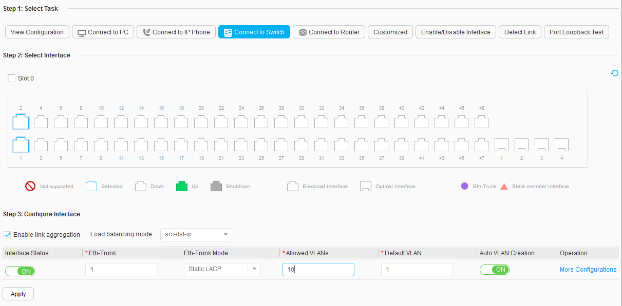
- Select Enable link aggregation in the Configure Interface area, and set parameters, as shown in Figure 4.
- Interface Status: ON
- Eth-Trunk: 1
- Eth-Trunk Mode: Static LACP
- Allowed VLANs: 10
- Default VLAN: 1
- Auto VLAN Creation: ON
- Click Apply. In the dialog box that is displayed, click OK.
- Configure interfaces of ACC1 connected to users and add users to a VLAN.
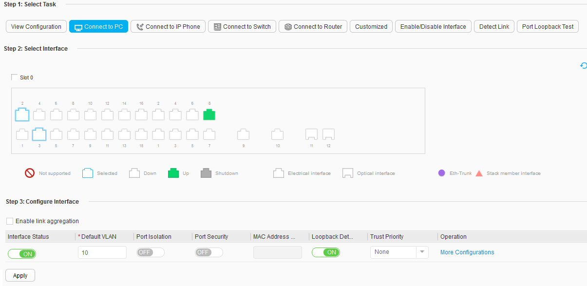
- Choose , and click Connect to PC in the Select Task area.
- Select Ethernet0/0/2 and Ethernet0/0/3 to be configured.
- Set parameters in the Configure Interface area, as shown in Figure 5.
- Interface Status: ON
- Default VLAN: 10
- Port Isolation: OFF
- Port Security: OFF
- Loopback Detection: OFF
- Trust Priority: None
- Click Apply. In the dialog box that is displayed, click OK.
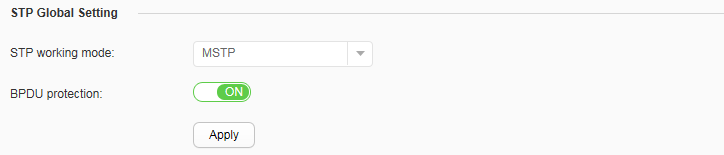
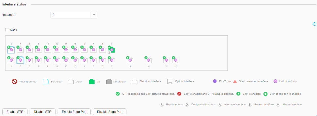
- Configure edge ports and the BPDU protection function.
- Configure Eth-Trunk 1 that connects ACC1 to CORE to transparently transmit packets from the VLAN of department A.
- Configure the interfaces and VLAN on the core switch.
- Configure downlink interfaces of the core switch. (The following uses the configuration of Eth-Trunk 1 that connects CORE to ACC1 as an example, and the configuration for connecting to ACC2 is similar.)
- Choose , and click Connect to Switch in the Select Task area.
- Select GigabitEthernet0/0/1 and GigabitEthernet0/0/2 to be configured.
- Select Enable link aggregation in the Configure Interface area, and set parameters, as shown in Figure 8.
- Interface Status: ON
- Eth-Trunk: 1
- Eth-Trunk Mode: Static LACP
- Allowed VLANs: 10
- Default VLAN: 1
- Auto VLAN Creation: ON
- Click Apply. In the dialog box that is displayed, click OK.
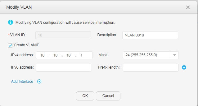
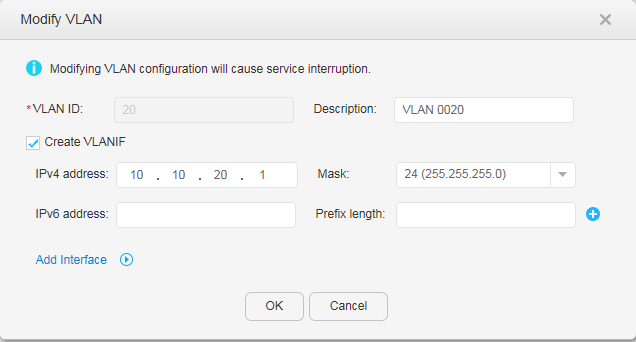
- Configure VLANIF interfaces for departments A and B to communicate with each other.
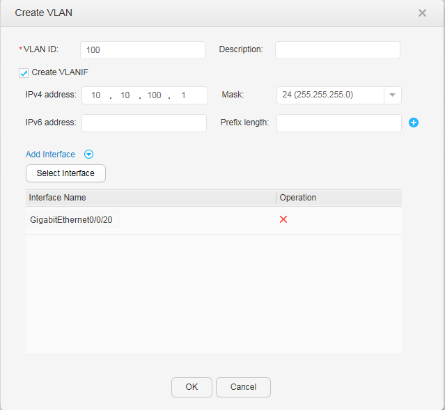
- Configure uplink interfaces and VLANIF interfaces of the core switch for communication between the campus network and the Internet.
- Choose to access the VLAN configuration page.
- Click Create. In the Create VLAN dialog box, set parameters, as shown in Figure 11.
- VLAN ID: 100
- Select Create VLANIF
- IPv4 address: 10.10.100.1
- Mask: 24
- Add Interface: GigabitEthernet0/0/20
- Click OK.
- Configure downlink interfaces of the core switch. (The following uses the configuration of Eth-Trunk 1 that connects CORE to ACC1 as an example, and the configuration for connecting to ACC2 is similar.)
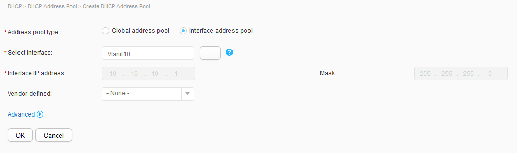
- Configure the DHCP server on the core switch.
Configure the DHCP server on CORE to assign IP address to users in departments A (VLAN 10) and B (VLAN 20).
- Click Create. In the Create DHCP Address Pool dialog box, set parameters, as shown in Figure 12. Click OK. Users in department A then can obtain IP addresses from the interface address pool on VLANIF 10.
- Address pool type: Interface address pool
- Select Interface: Vlanif10
- Use the same method to configure users in department B to obtain IP addresses from the interface address pool on VLANIF 20. The parameter settings are shown in Figure 13.
- Click Create. In the Create DHCP Address Pool dialog box, set parameters, as shown in Figure 12. Click OK. Users in department A then can obtain IP addresses from the interface address pool on VLANIF 10.
- Configure routes on the core switch.
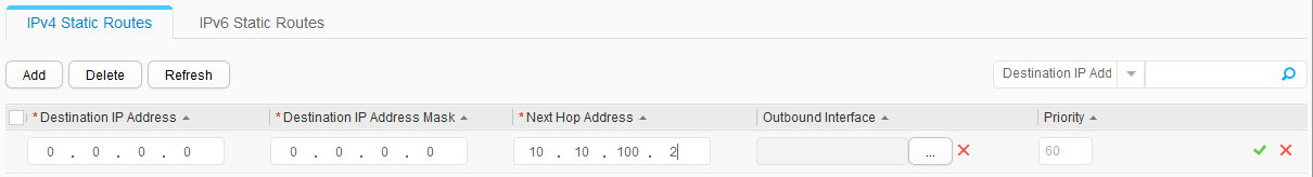
- Click Add and set the parameters, as shown in Figure 14.
- Destination IP Address: 0.0.0.0
- Destination IP Address Mask: 0.0.0.0
- Next Hop Address: 10.10.100.2
- Click
 .
.
- Click Add and set the parameters, as shown in Figure 14.
- Configure an egress router. (The following uses an AR router in V200R009C00 as an example. For details about how to log in to the web system of an AR router, see the corresponding documentation.)
Before configuring the egress router, you need the following data: IP address of the public network interface (1.1.1.2/30), IP address of the public network gateway (1.1.1.1), and DNS server address (2.2.2.2). These parameters are provided by carriers when the broadband service is applied. The data used in this example is for reference only.
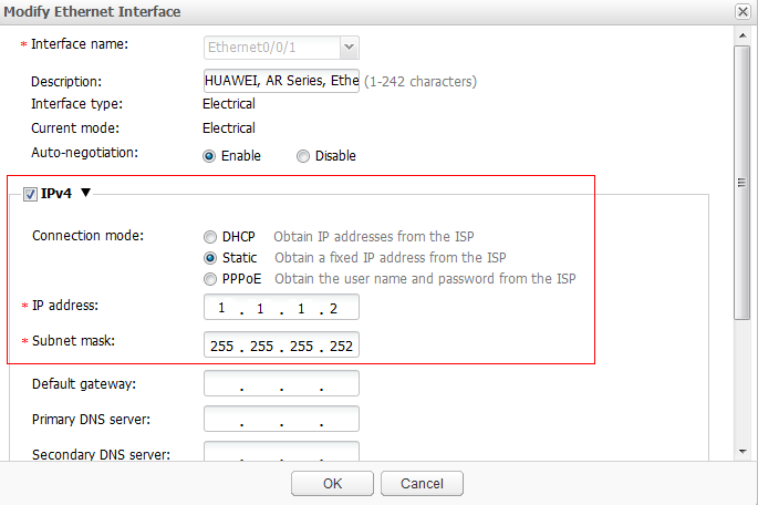
- Configure IP addresses of the intranet and public network interfaces on the egress router.
- Choose . The Ethernet Interface tab page is displayed.
- In the Ethernet Interface List area, click
 in the Ethernet0/0/1 column. The Modify Ethernet Interface dialog box is displayed.
 - Set parameters, as shown in Figure 15. Click OK. The IP address of the public network interface is configured.
- Select IPv4.
- Connection mode: Static
- IP address: 1.1.1.2
- Subnet mask: 255.255.255.252
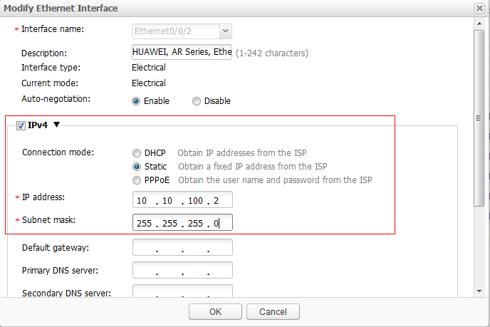
- Use the same method to configure an IP address for the intranet interface. The parameter settings are shown in Figure 16.
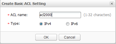
- Configure an ACL that allows users to connect to the Internet.
- Choose . The Basic ACL Setting tab page is displayed.
- Click Create. The Create Basic ACL Setting dialog box is displayed.
- Set parameters, as shown in Figure 17. Click OK. The basic ACL is created.
- ACL name: acl2000
- Type: IPv4
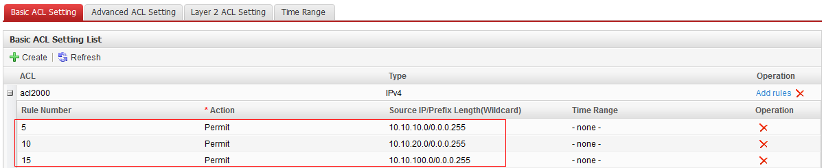
- Click Add rules in the acl2000 column, and set parameters, as shown in Figure 18. Click .
ACL Rule ID
Action
Source IP Address/Prefix Length (Wildcard)
5
Permit
10.10.10.0/0.0.0.255
10
Permit
10.10.20.0/0.0.0.255
15
Permit
10.10.100.0/0.0.0.255
- Configure NAT on the interface that connects to the public network so that intranet users can access the Internet.
- Choose . The External Network Access tab page is displayed.
- Click Create. The Create External Network Access dialog box is displayed.
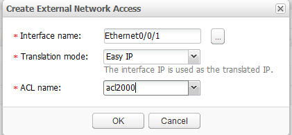
- Set parameters, as shown in Figure 19. Click OK.
- Interface name: Ethernet0/0/1
- Translation mode: Easy IP
- ACL name: acl2000
- Configure a specific route to the intranet and a default static route to the public network.
- Choose . The Static Route Configuration tab page is displayed.
- In the IPv4 Static Route Configuration Table area, click Create. The Create IPv4 Static Route Service dialog box is displayed.
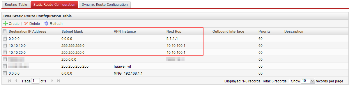
- Set parameters, as shown in Figure 20. Click OK.
Destination IP Address
Subnet Mask
Next Hop
10.10.10.0
255.255.255.0
10.10.100.1
10.10.20.0
255.255.255.0
10.10.100.1
0.0.0.0
0.0.0.0
1.1.1.1
- Configure the DNS server function.
- Choose . The DNS tab page is displayed.
- In the DNS Setting area, click Enabled for DNS proxy(IPv4), and click Apply.
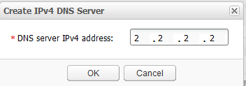
- In the DNS Server Configuration List(IPv4 Address) area, click Create. The Create IPv4 DNS Server dialog box is displayed.
- Set DNS server IPv4 address to 2.2.2.2, as shown in Figure 21. Click OK.
- Configure IP addresses of the intranet and public network interfaces on the egress router.
- Configure DHCP snooping and IPSG on access switches.
After the DHCP function is configured, intranet users in departments can automatically obtain IP addresses. To prevent intranet users from connecting to an unauthorized router and enabling the DHCP function, configure the DHCP snooping function so that intranet valid users can connect to the Internet successfully. Additionally, to prevent intranet users from changing their IP addresses to attack the network, enable the IPSG function on access switches. ACC1 is used as an example.
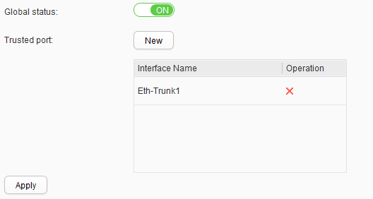
- Configure the DHCP snooping function.
- Choose . The DHCP Snooping tab page is displayed.
- Set Global status to ON.
- Add Eth-Trunk1 to Trusted port, as shown in Figure 22. Click Apply.
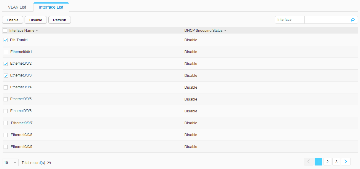
- In the Interface List area, select Eth-Trunk1, Ethernet0/0/2, and Ethernet0/0/3, and click Enable, as shown in Figure 23. The DHCP snooping function is enabled on the interface that connects to the DHCP server and the interface that connects to terminals.
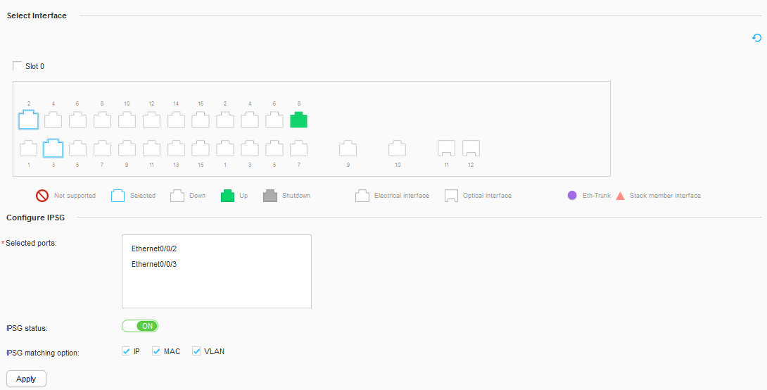
- Enable the IPSG function.
- Choose . The IPSG tab page is displayed.
- Select Ethernet0/0/2 and Ethernet0/0/3 in the Select Interface area.
- Set parameters in the Configure IPSG area, as shown in Figure 24. Click Apply.
- IPSG status: ON
- IPSG matching option: IP, MAC, and VLAN
- Configure the DHCP snooping function.
- Save the configuration.
Click Save in the upper right corner. The system saves all configurations to the configuration file.


Service Verification
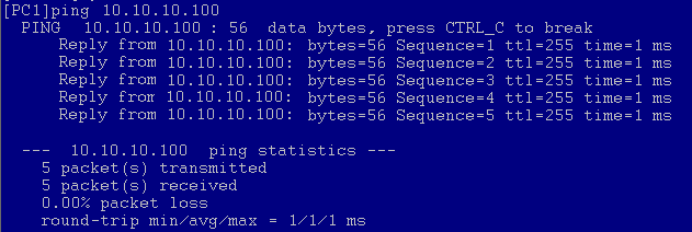
- Select two PCs in a department to perform a ping test to verify Layer 2 communication.
Use department A as an example, and assume that the IP address obtained by PC2 through DHCP is 10.10.10.100. Figure 25 shows the test result.
- Select one PC in each department to perform a ping test to verify Layer 3 communication through VLANIF interfaces.
Users in departments A and B communicate with each other at Layer 3 through VLANIF interfaces of CORE. If the ping test between PC1 and PC3 succeeds, these two departments can communicate with each other at Layer 3 through VLANIF interfaces. The ping command is similar to that in the first step.
- Select one PC in each department to perform a ping test to a public IP address to check whether intranet users can access the Internet normally.
Use department A as an example, and ping the IP address of the public network gateway (IP address of the carrier's device connected to the egress router) from PC1 to check whether intranet users can access the Internet. If the ping test succeeds, intranet users can access the Internet normally. The ping command is similar to that in the first step.