Example for Configuring the Soft GRE Service
Service Requirements
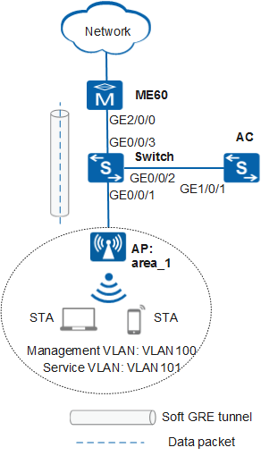
Enterprise users can access the network through WLANs, which is the basic requirement of mobile office. Furthermore, users' services are not affected during roaming in the coverage area. A wired network has been deployed in an area. To provide more convenient network access services, administrators need to deploy a wireless network in this area. To facilitate the unified management of wired and wireless users, administrators also need to use the existing wired access gateway ME60 for authentication and accounting of wireless users.
Networking Requirements
- AC networking mode: Layer 2 networking in bypass mode
- DHCP deployment mode:
- The ME60 functions as a DHCP server to assign IP addresses to STAs.
- Switch functions as a DHCP server to assign IP addresses to APs.
- Service data forwarding mode: soft GRE forwarding
Data Planning
Item |
Data |
|---|---|
Switch data planning |
|
DHCP server |
Switch functions as a DHCP server to assign IP addresses to APs. |
IP address pool for APs |
10.23.100.3-10.23.100.254/24 |
AC data planning |
|
AC's source interface address |
VLANIF 100: 10.23.100.1/24 |
AP group |
|
Regulatory domain profile |
|
SSID profile |
|
Security profile |
|
Soft GRE profile |
|
VAP profile |
|
ME60 data planning |
|
DHCP server |
The ME60 functions as a DHCP server to assign IP addresses to STAs. |
IP address pool for STAs |
10.23.101.2-10.23.101.254/24 |
VE interface for soft GRE |
Virtual-Ethernet2/0/0 |
Soft GRE group |
|
Destination address of the soft GRE tunnel |
|
RADIUS server parameters |
|
Configuration Roadmap
- Configure network interworking of the APs, AC, Switch, and ME60.
- Configure Switch and ME60 to function as DHCP servers to assign IP addresses to APs and STAs, respectively.
- Configure the ME60, soft GRE tunnel, and authentication and accounting functions.
- Configure the APs to go online.
- Create an AP group and add APs that require the same configuration to the group for unified configuration.
- Configure AC system parameters, including the country code and source interface used by the AC to communicate with the APs.
- Configure the AP authentication mode and import the APs offline to allow the APs to go online.
- Configure WLAN service parameters.
Configuration Notes
- No ACK mechanism is provided for multicast packet transmission on air interfaces. In addition, wireless links are unstable. To ensure stable transmission of multicast packets, they are usually sent at low rates. If a large number of such multicast packets are sent from the network side, the air interfaces may be congested. You are advised to configure multicast packet suppression to reduce impact of a large number of low-rate multicast packets on the wireless network. Exercise caution when configuring the rate limit; otherwise, the multicast services may be affected.
- In direct forwarding mode, you are advised to configure multicast packet suppression on switch interfaces connected to APs.
- In tunnel forwarding mode, you are advised to configure multicast packet suppression in traffic profiles of the AC.
Configure port isolation on the interfaces of the device directly connected to APs. If port isolation is not configured and direct forwarding is used, a large number of unnecessary broadcast packets may be generated in the VLAN, blocking the network and degrading user experience.
In tunnel forwarding mode, the management VLAN and service VLAN cannot be the same. Only packets from the management VLAN are transmitted between the AC and APs. Packets from the service VLAN are not allowed between the AC and APs.
Procedure
- Configure the network devices.
# On Switch, add GE0/0/1 to VLAN 100 and VLAN 101, GE0/0/2 to VLAN 100, and GE0/0/3 to VLAN 199. Set the PVIDs of GE0/0/1 and GE0/0/3 to VLAN 100 and VLAN 199, respectively. Create VLANIF 199 and set its IP address to 10.23.199.2/24.
<HUAWEI> system-view
[HUAWEI] sysname Switch
[Switch] vlan batch 100 101 199
[Switch] interface gigabitethernet 0/0/1
[Switch-GigabitEthernet0/0/1] port link-type trunk
[Switch-GigabitEthernet0/0/1] port trunk allow-pass vlan 100 101
[Switch-GigabitEthernet0/0/1] port trunk pvid vlan 100
[Switch-GigabitEthernet0/0/1] undo port trunk allow-pass vlan 1
[Switch-GigabitEthernet0/0/1] stp edged-port enable
[Switch-GigabitEthernet0/0/1] port-isolate enable
[Switch-GigabitEthernet0/0/1] quit
[Switch] interface gigabitethernet 0/0/2
[Switch-GigabitEthernet0/0/2] port link-type trunk
[Switch-GigabitEthernet0/0/2] port trunk allow-pass vlan 100
[Switch-GigabitEthernet0/0/2] undo port trunk allow-pass vlan 1
[Switch-GigabitEthernet0/0/2] quit
[Switch] interface gigabitethernet 0/0/3
[Switch-GigabitEthernet0/0/3] port link-type trunk
[Switch-GigabitEthernet0/0/3] port trunk allow-pass vlan 199
[Switch-GigabitEthernet0/0/3] port trunk pvid vlan 199
[Switch-GigabitEthernet0/0/3] undo port trunk allow-pass vlan 1
[Switch-GigabitEthernet0/0/3] quit
[Switch] interface vlanif 199
[Switch-Vlanif199] ip address 10.23.199.2 24
[Switch-Vlanif199] quit
# On the ME60, set the IP address of GE2/0/0 to 10.23.199.1/24, and configure a route to 10.23.100.0/24.
<HUAWEI> system-view
[HUAWEI] sysname ME60
[ME60] interface gigabitethernet 2/0/0
[ME60-GigabitEthernet2/0/0] ip address 10.23.199.1 24
[ME60-GigabitEthernet2/0/0] quit
[ME60] ip route-static 10.23.100.0 24 10.23.199.2
- Configure the AC to communicate with the network devices.# On the AC, add GE1/0/1 to VLAN 100 (management VLAN). Create VLANIF 100 and set its IP address to 10.23.100.1/24.
<HUAWEI> system-view
[HUAWEI] sysname AC
[AC] vlan batch 100 101
[AC] interface gigabitethernet 1/0/1
[AC-GigabitEthernet1/0/1] port link-type trunk
[AC-GigabitEthernet1/0/1] port trunk allow-pass vlan 100
[AC-GigabitEthernet1/0/1] undo port trunk allow-pass vlan 1
[AC-GigabitEthernet1/0/1] quit
[AC] interface vlanif 100
[AC-Vlanif100] ip address 10.23.100.1 24
[AC-Vlanif100] quit
- Configure the DHCP servers to assign IP addresses to APs and STAs.
# Configure Switch as a DHCP server to assign IP addresses to APs, and configure a route to 10.23.200.0/24.
[Switch] dhcp enable
[Switch] interface vlanif 100
[Switch-Vlanif100] ip address 10.23.100.2 24
[Switch-Vlanif100] dhcp select interface
[Switch-Vlanif100] dhcp server excluded-ip-address 10.23.100.1
[Switch-Vlanif100] quit
[Switch] ip route-static 10.23.200.0 24 10.23.199.1
# Configure the ME60 as a DHCP server to assign IP addresses to STAs.
 Configure the DNS server as required. The common methods are as follows:
- In interface address pool scenarios, run the dhcp server dns-list ip-address &<1-8> command in the VLANIF interface view.
- In global address pool scenarios, run the dns-list ip-address &<1-8> command in the IP address pool view.
[ME60] dhcp enable
[ME60] ip pool sta-pool bas local
[ME60-ip-pool-sta-pool] gateway 10.23.101.1 24
[ME60-ip-pool-sta-pool] section 1 10.23.101.3 10.23.101.254
[ME60-ip-pool-sta-pool] option 43 ip 10.23.101.1
[ME60-ip-pool-sta-pool] quit
- Configure the soft GRE tunnel on the ME60.
# Create a VE interface to support soft GRE.
[ME60] interface virtual-ethernet 2/0/0
[ME60-Virtual-Ethernet2/0/0] soft-gre enable
[ME60-Virtual-Ethernet2/0/0] quit
# Create a soft GRE group.
[ME60] soft-gre group group1
[ME60-softgre-group-group1] master virtual-ethernet 2/0/0
[ME60-softgre-group-group1] quit
# Configure an IP address for the loopback interface and bind the soft GRE group to it.
[ME60] interface loopback 1
[ME60-LoopBack1] ip address 10.23.200.1 255.255.255.0
[ME60-LoopBack1] binding soft-gre group group1
[ME60-LoopBack1] quit
- Configure RADIUS authentication and accounting on the ME60.
# Configure a RADIUS server profile, an AAA authentication and accounting scheme, and domain information.
[ME60] radius-server group radius1
[ME60-radius-radius1] radius-server authentication 10.1.1.1 1812
[ME60-radius-radius1] radius-server accounting 10.1.1.1 1813
[ME60-radius-radius1] radius-server shared-key 123456
[ME60-radius-radius1] quit
[ME60] aaa
[ME60-aaa] authentication-scheme radius
[ME60-aaa-authen-radius] authentication-mode radius
[ME60-aaa-authen-radius] quit
[ME60-aaa] accounting-scheme radius
[ME60-aaa-accounting-radius] accounting-mode radius
[ME60-aaa-accounting-radius] quit
[ME60-aaa] domain aaadomain1
[ME60-aaa-domain-aaadomain1] ip-pool sta-pool
[ME60-aaa-domain-aaadomain1] authentication-scheme radius
[ME60-aaa-domain-aaadomain1] accounting-scheme radius
[ME60-aaa-domain-aaadomain1] radius-server group radius1
[ME60-aaa-domain-aaadomain1] quit
[ME60-aaa] quit
- Configure the BAS interface on the ME60.
# Create a BAS interface and configure the BAS interface type and authentication mode. Configure the user VLAN and service VLAN as the same VLAN.
[ME60] interface virtual-ethernet 2/0/0.1
[ME60-Virtual-Ethernet2/0/0.1] user-vlan 101
[ME60-Virtual-Ethernet2/0/0.1-vlan-101-101] bas
[ME60-Virtual-Ethernet2/0/0.1-bas] access-type layer2-subscriber default-domain authentication aaadomain1
[ME60-Virtual-Ethernet2/0/0.1-bas] authentication-method bind
- Configure an AP to go online.# Create an AP group to which the APs with the same configuration can be added.
[AC] wlan
[AC-wlan-view] ap-group name ap-group1
[AC-wlan-ap-group-ap-group1] quit
# Create a regulatory domain profile, configure the AC country code in the profile, and apply the profile to the AP group.[AC-wlan-view] regulatory-domain-profile name default [AC-wlan-regulate-domain-default] country-code cn [AC-wlan-regulate-domain-default] quit [AC-wlan-view] ap-group name ap-group1 [AC-wlan-ap-group-ap-group1] regulatory-domain-profile default Warning: Modifying the country code will clear channel, power and antenna gain configurations of the radio and reset the AP. Continue?[Y/N]:y [AC-wlan-ap-group-ap-group1] quit [AC-wlan-view] quit
# Configure the AC's source interface.[AC] capwap source interface vlanif 100
# Import the AP offline on the AC and add the AP to AP group ap-group1. Assume that the AP's MAC address is 60de-4476-e360. Configure a name for the AP based on the AP's deployment location, so that you can know where the AP is deployed from its name. For example, name the AP area_1 if it is deployed in Area 1. The default AP authentication mode is MAC address authentication. If the default settings are retained, you do not need to run the ap auth-mode mac-auth command.
In this example, the AP5030DN is used and has two radios: radio 0 (2.4 GHz radio) and radio 1 (5 GHz radio).
[AC] wlan
[AC-wlan-view] ap auth-mode mac-auth
[AC-wlan-view] ap-id 0 ap-mac 60de-4476-e360
[AC-wlan-ap-0] ap-name area_1
[AC-wlan-ap-0] ap-group ap-group1
Warning: This operation may cause AP reset. If the country code changes, it will clear channel, power and antenna gain configuration s of the radio, Whether to continue? [Y/N]:y
[AC-wlan-ap-0] quit
# After the AP is powered on, run the display ap all command to check the AP state. If the State field is displayed as nor, the AP goes online successfully.[AC-wlan-view] display ap all Total AP information: nor : normal [1] Extrainfo : Extra information P : insufficient power supply -------------------------------------------------------------------------------------------------- ID MAC Name Group IP Type State STA Uptime ExtraInfo -------------------------------------------------------------------------------------------------- 0 60de-4476-e360 area_1 ap-group1 10.23.100.254 AP5030DN nor 0 10S --------------------------------------------------------------------------------------------------- Total: 1
- Configure WLAN service parameters.
# Create security profile wlan-net and use the default security policy in the profile.
[AC-wlan-view] security-profile name wlan-net
[AC-wlan-sec-prof-wlan-net] quit
# Create SSID profile wlan-net and set the SSID name to wlan-net.[AC-wlan-view] ssid-profile name wlan-net [AC-wlan-ssid-prof-wlan-net] ssid wlan-net [AC-wlan-ssid-prof-wlan-net] quit
# Create soft GRE profile wlan-soft and set the soft GRE profile parameters.
[AC-wlan-view] softgre-profile name wlan-soft
[AC-wlan-softgre-prof-wlan-soft] destination ip-address 10.23.200.1
[AC-wlan-softgre-prof-wlan-soft] quit
# Create VAP profile wlan-net, set the data forwarding mode and service VLAN, and apply the security profile and SSID profile to the VAP profile.
[AC-wlan-view] vap-profile name wlan-net
[AC-wlan-vap-prof-wlan-net] forward-mode softgre wlan-soft
[AC-wlan-vap-prof-wlan-net] service-vlan vlan-id 101
[AC-wlan-vap-prof-wlan-net] security-profile wlan-net
[AC-wlan-vap-prof-wlan-net] ssid-profile wlan-net
[AC-wlan-vap-prof-wlan-net] quit
# Bind VAP profile wlan-net to the AP group and apply the profile to radio 0 and radio 1 of the AP.[AC-wlan-view] ap-group name ap-group1 [AC-wlan-ap-group-ap-group1] vap-profile wlan-net wlan 1 radio 0 [AC-wlan-ap-group-ap-group1] vap-profile wlan-net wlan 1 radio 1 [AC-wlan-ap-group-ap-group1] quit
- Configure the AP channel and power.
Automatic channel and power calibration functions are enabled by default. The manual channel and power configurations take effect only when these two functions are disabled. The settings of the AP channel and power in this example are for reference only. You need to configure the AP channel and power based on the actual country code and network planning.
# Disable automatic channel and power calibration functions of radio 0, and configure the channel and power for radio 0.[AC-wlan-view] ap-id 0 [AC-wlan-ap-0] radio 0 [AC-wlan-radio-0/0] calibrate auto-channel-select disable [AC-wlan-radio-0/0] calibrate auto-txpower-select disable [AC-wlan-radio-0/0] channel 20mhz 6 Warning: This action may cause service interruption. Continue?[Y/N]y [AC-wlan-radio-0/0] eirp 127 [AC-wlan-radio-0/0] quit# Disable automatic channel and power calibration functions of radio 1, and configure the channel and power for radio 1.[AC-wlan-ap-0] radio 1 [AC-wlan-radio-0/1] calibrate auto-channel-select disable [AC-wlan-radio-0/1] calibrate auto-txpower-select disable [AC-wlan-radio-0/1] channel 20mhz 149 Warning: This action may cause service interruption. Continue?[Y/N]y [AC-wlan-radio-0/1] eirp 127 [AC-wlan-radio-0/1] quit [AC-wlan-ap-0] quit - Verify the configuration.
The AC automatically delivers WLAN service configuration to the AP. After the configuration is complete, run the display vap ssid wlan-net command. If the Status field is displayed as ON, the VAPs have been successfully created on AP radios.
[AC-wlan-view] display vap ssid wlan-net
WID : WLAN ID
--------------------------------------------------------------------------------
AP ID AP name RfID WID   BSSID          Status  Auth type     STA   SSID
--------------------------------------------------------------------------------
0     area_1  0    1     60DE-4476-E360 ON      open          0     wlan-net
0     area_1  1    1     60DE-4476-E370 ON      open          0     wlan-net
-------------------------------------------------------------------------------
Total: 2
Connect STAs to the WLAN with SSID wlan-net. Run the display station ssid wlan-net command on the AC. The command output shows that the STAs are connected to the WLAN wlan-net.
[AC-wlan-view] display station ssid wlan-net
Rf/WLAN: Radio ID/WLAN ID
Rx/Tx: link receive rate/link transmit rate(Mbps)
---------------------------------------------------------------------------------
STA MAC         AP ID Ap name   Rf/WLAN  Band  Type  Rx/Tx      RSSI  VLAN  IP address
---------------------------------------------------------------------------------
e019-1dc7-1e08  0     area_1    1/1      5G    11n   46/59      -68   101   10.23.101.254
---------------------------------------------------------------------------------
Total: 1 2.4G: 0 5G: 1
Configuration Files
Switch configuration file
#
sysname Switch
#
vlan batch 100 to 101 199
#
dhcp enable
#
interface Vlanif100
 ip address 10.23.100.2 255.255.255.0
 dhcp select interface
 dhcp server excluded-ip-address 10.23.100.1
#
interface Vlanif199
 ip address 10.23.199.2 255.255.255.0
#
interface GigabitEthernet0/0/1
 port link-type trunk
 port trunk pvid vlan 100
 undo port trunk allow-pass vlan 1
 port trunk allow-pass vlan 100 to 101
 stp edged-port enable
 port-isolate enable group 1
#
interface GigabitEthernet0/0/2
 port link-type trunk
 undo port trunk allow-pass vlan 1
 port trunk allow-pass vlan 100
#
interface GigabitEthernet0/0/3
 port link-type trunk
 port trunk pvid vlan 199
 undo port trunk allow-pass vlan 1
 port trunk allow-pass vlan 199
#
ip route-static 10.23.200.0 255.255.255.0 10.23.199.1
#
return
AC configuration file
#
 sysname AC
#
vlan batch 100 to 101
#
interface Vlanif100
 ip address 10.23.100.1 255.255.255.0
#
interface GigabitEthernet1/0/1
 port link-type trunk
 undo port trunk allow-pass vlan 1
 port trunk allow-pass vlan 100
#
capwap source interface vlanif100
#
wlan
 security-profile name wlan-net
 ssid-profile name wlan-net
  ssid wlan-net
 softgre-profile name wlan-soft
  destination ip-address 10.23.200.1
 vap-profile name wlan-net
  forward-mode softgre wlan-soft
  service-vlan vlan-id 101
  ssid-profile wlan-net
  security-profile wlan-net
 regulatory-domain-profile name default
 ap-group name ap-group1
  radio 0
   vap-profile wlan-net wlan 1
  radio 1
   vap-profile wlan-net wlan 1
 ap-id 0 type-id 35 ap-mac 60de-4476-e360 ap-sn 210235554710CB000042
  ap-name area_1
  ap-group ap-group1
  radio 0
   channel 20mhz 6
   eirp 127
   calibrate auto-channel-select disable
  calibrate auto-txpower-select disable
  radio 1
   channel 20mhz 149
   eirp 127
   calibrate auto-channel-select disable
   calibrate auto-txpower-select disable
#
return
ME60 configuration file
#
sysname ME60
#
vlan batch 101
#
radius-server group radius1
 radius-server authentication 10.1.1.1 1812 weight 0
 radius-server accounting 10.1.1.1 1813 weight 0
 radius-server shared-key 123456
#
ip pool sta-pool bas local
 gateway 10.23.101.1 255.255.255.0
 section 1 10.23.101.3 10.23.101.254
 option 43 ip 10.23.101.1
#
aaa
 authentication-scheme radius
 #
 accounting-scheme radius
 #
 domain aaadomain1
  authentication-scheme radius
  accounting-scheme radius
  ip-pool sta-pool
  radius-server group radius1
 #
#
interface GigabitEthernet2/0/0
 undo shutdown
 ip address 10.23.199.1 255.255.255.0
#
interface Virtual-Ethernet2/0/0
 soft-gre enable
#
interface Virtual-Ethernet2/0/0.1
 user-vlan 101
 bas
 #
  access-type layer2-subscriber default-domain authentication aaadomain1
  authentication-method bind
 #
#
interface LoopBack1
 ip address 10.23.200.1 255.255.255.0
 binding soft-gre group group1
#
soft-gre group group1
 master Virtual-Ethernet2/0/0
#
ip route-static 10.23.100.0 255.255.255.0 10.23.199.2
#
return