Example for Configuring an Agile Distributed WLAN
Configuration Process
You need to configure and maintain WLAN features and functions in different profiles. These WLAN profiles include regulatory domain profile, radio profile, VAP profile, AP system profile, AP wired port profile, WIDS profile, WDS profile, and Mesh profile. When configuring WLAN services, you need to set related parameters in the WLAN profiles and bind the profiles to the AP group or APs. Then the configuration is automatically delivered to and takes effect on the APs. WLAN profiles can reference one another; therefore, you need to know the relationships among the profiles before configuring them. For details about the profile relationships and their basic configuration procedure, see WLAN Service Configuration Procedure.
Networking Requirements
A school plans to deploy a WLAN to cover its dormitory building. However, the dormitory building has a high density of rooms, and WLAN signals are likely to attenuate severely when passing through obstacles between rooms, such as walls.
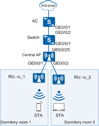
As shown in Figure 1, the AC connects to a central AP through the switch, and the central AP connects to and supplies PoE power for remote units (RUs). All RUs (one for each room) and the central AP are uniformly managed by the AC to provide a high-quality WLAN.
Configuration Roadmap
The configuration roadmap is as follows:
- Configure the central AP, RUs, Switch, AC, and upper-layer devices to communicate at Layer 2.
- Configure the AC as a DHCP server to assign IP addresses to the central AP, RUs, and STAs.
- Configure the central AP and RUs to go online.
- Create an AP group and add the central AP and RUs that require the same configuration to the group for unified configuration.
- Configure AC system parameters, including the country code and source interface.
- Configure the AP authentication mode and import the central AP and RUs offline so that they can go online normally.
- Configure WLAN service parameters for STAs to access the WLAN.
Item |
Data |
|---|---|
DHCP server |
The AC works as a DHCP server to assign IP addresses to the central AP, RUs, and STAs. |
IP address pool for the central AP and RUs |
10.23.100.2-10.23.100.254/24 |
IP address pool for the STAs |
10.23.101.2-10.23.101.254/24 |
IP address of the AC's source interface |
VLANIF 100: 10.23.100.1/24 |
AP group |
|
Regulatory domain profile |
|
SSID profile |
|
Security profile |
|
VAP profile |
|
Configuration Notes
For details about common WLAN configuration notes, see General Precautions for WLAN. For more deployment and configuration suggestions, see Wireless Network Deployment and Configuration Suggestions.
- No ACK mechanism is provided for multicast packet transmission on air interfaces. In addition, wireless links are unstable. To ensure stable transmission of multicast packets, they are usually sent at low rates. If a large number of such multicast packets are sent from the network side, the air interfaces may be congested. You are advised to configure multicast packet suppression to reduce impact of a large number of low-rate multicast packets on the wireless network. Exercise caution when configuring the rate limit; otherwise, the multicast services may be affected.
- In direct forwarding mode, you are advised to configure multicast packet suppression on switch interfaces connected to APs.
- In tunnel forwarding mode, you are advised to configure multicast packet suppression in traffic profiles of the AC.
Configure port isolation on the interfaces of the device directly connected to APs. If port isolation is not configured and direct forwarding is used, a large number of unnecessary broadcast packets may be generated in the VLAN, blocking the network and degrading user experience.
In tunnel forwarding mode, the management VLAN and service VLAN cannot be the same. Only packets from the management VLAN are transmitted between the AC and APs. Packets from the service VLAN are not allowed between the AC and APs.
Procedure
- Set the NAC mode to unified on the AC so that users can connect to the network properly.
<HUAWEI> system-view
[HUAWEI] authentication unified-mode

If the NAC mode is changed from traditional to unified, the unified mode takes effect after you save the configuration and restart the device.
- Configure the AC and switch to enable it to transmit CAPWAP packets to the central AP and RUs.
# Add GE0/0/1 that connects Switch to the AP to management VLAN 100 and add GE0/0/2 that connects Switch to the AC to the same VLAN.
<HUAWEI> system-view
[HUAWEI] sysname SwitchA
[SwitchA] vlan batch 100
[SwitchA] interface gigabitethernet 0/0/1
[SwitchA-GigabitEthernet0/0/1] port link-type trunk
[SwitchA-GigabitEthernet0/0/1] port trunk pvid vlan 100
[SwitchA-GigabitEthernet0/0/1] port trunk allow-pass vlan 100
[SwitchA-GigabitEthernet0/0/1] port-isolate enable
[SwitchA-GigabitEthernet0/0/1] quit
[SwitchA] interface gigabitethernet 0/0/2
[SwitchA-GigabitEthernet0/0/2] port link-type trunk
[SwitchA-GigabitEthernet0/0/2] port trunk allow-pass vlan 100
[SwitchA-GigabitEthernet0/0/2] quit
# Add GE0/0/1 that connects the AC to SwitchA to VLAN 100.
[HUAWEI] sysname AC
[AC] vlan batch 100 101
[AC] interface gigabitethernet 0/0/1
[AC-GigabitEthernet0/0/1] port link-type trunk
[AC-GigabitEthernet0/0/1] port trunk allow-pass vlan 100
[AC-GigabitEthernet0/0/1] quit
- Configure the AC to communicate with upper-layer network devices.
# Configure the AC to communicate with upper-layer network devices according to your network requirements (the configuration procedure is not provided here).
- Configure the AC as a DHCP server to assign IP addresses to the central AP, RUs, and STAs.
# Configure the AC as a DHCP server to allocate IP addresses to the central AP and RUs from the IP address pool on VLANIF 100, and allocate IP addresses to STAs from the IP address pool on VLANIF 101.
Configure the DNS server as required. The common methods are as follows:- In interface address pool scenarios, run the dhcp server dns-list ip-address &<1-8> command in the VLANIF interface view.
- In global address pool scenarios, run the dns-list ip-address &<1-8> command in the IP address pool view.
[AC] dhcp enable
[AC] interface vlanif 100
[AC-Vlanif100] ip address 10.23.100.1 24
[AC-Vlanif100] dhcp select interface
[AC-Vlanif100] quit
[AC] interface vlanif 101
[AC-Vlanif101] ip address 10.23.101.1 24
[AC-Vlanif101] dhcp select interface
[AC-Vlanif101] quit
- Configure the central AP and RUs to go online.
# Create an AP group to which the central AP and RUs with the same configuration can be added.
[AC] wlan
[AC-wlan-view] ap-group name ap-group1
[AC-wlan-ap-group-ap-group1] quit
# Create a regulatory domain profile, configure the AC country code in the profile, and apply the profile to the AP group.
[AC-wlan-view] regulatory-domain-profile name domain1
[AC-wlan-regulate-domain-domain1] country-code cn
[AC-wlan-regulate-domain-domain1] quit
[AC-wlan-view] ap-group name ap-group1
[AC-wlan-ap-group-ap-group1] regulatory-domain-profile domain1
Warning: Modifying the country code will clear channel, power and antenna gain configurations of the radio and reset the AP. Continue?[Y/N]:y
[AC-wlan-ap-group-ap-group1] quit
[AC-wlan-view] quit
# Configure the AC's source interface.
[AC] capwap source interface vlanif 100
# Import the central AP and RUs offline on the AC and add the central AP and RUs to the AP group ap-group1. Assume that the central AP has the MAC address 68a8-2845-62fd and is named central_AP, and two RUs have the MAC addresses fcb6-9897-c520 and fcb6-9897-ca40, and are named rru_1 and rru_2. The default AP authentication mode is MAC address authentication. If the default settings are retained, you do not need to run the ap auth-mode mac-auth command.
[AC] wlan
[AC-wlan-view] ap auth-mode mac-auth
[AC-wlan-view] ap-id 0 ap-mac 68a8-2845-62fd
[AC-wlan-ap-0] ap-name central_AP
Warning: This operation may cause AP reset. Continue? [Y/N]:y
[AC-wlan-ap-0] ap-group ap-group1
Warning: This operation may cause AP reset. If the country code changes, it will clear channel, power and antenna gain configuration s of the radio, Whether to continue? [Y/N]:y
[AC-wlan-ap-0] quit
[AC-wlan-view] ap-id 1 ap-mac fcb6-9897-c520
[AC-wlan-ap-1] ap-name rru_1
Warning: This operation may cause AP reset. Continue? [Y/N]:y
[AC-wlan-ap-1] ap-group ap-group1
Warning: This operation may cause AP reset. If the country code changes, it will clear channel, power and antenna gain configuration s of the radio, Whether to continue? [Y/N]:y
[AC-wlan-ap-1] quit
[AC-wlan-view] ap-id 2 ap-mac fcb6-9897-ca40
[AC-wlan-ap-2] ap-name rru_2
Warning: This operation may cause AP reset. Continue? [Y/N]:y
[AC-wlan-ap-2] ap-group ap-group1
Warning: This operation may cause AP reset. If the country code changes, it will clear channel, power and antenna gain configuration s of the radio, Whether to continue? [Y/N]:y
[AC-wlan-ap-2] quit
# After the central AP and RUs are powered on, run the display ap all command to check their states. If the State field displays nor, the central AP and RUs have gone online.
[AC-wlan-view] display ap all
Total AP information:
nor  : normal          [3]
Extrainfo : Extra information
P  : insufficient power supply
----------------------------------------------------------------------------------------------------------
ID   MAC            Name       Group     IP            Type            State STA Uptime      ExtraInfo
----------------------------------------------------------------------------------------------------------
0    68a8-2845-62fd central_AP ap-group1 10.23.100.254 AD9430DN-24     nor   0   2M:25S      -
1    fcb6-9897-c520 rru_1      ap-group1 10.23.100.253 R240D           nor   0   3M:5S       -
2    fcb6-9897-ca40 rru_2      ap-group1 10.23.100.252 R240D           nor   0   3M:14S      -
----------------------------------------------------------------------------------------------------------
Total: 3
- Configure WLAN service parameters.# Create the security profile wlan-security and set the security policy in the profile.
In this example, the security policy is set to WPA2+PSK+AES and password to a1234567. In actual situations, the security policy must be configured according to service requirements.
[AC-wlan-view] security-profile name wlan-security
[AC-wlan-sec-prof-wlan-security] security wpa2 psk pass-phrase a1234567 aes
[AC-wlan-sec-prof-wlan-security] quit
# Create the SSID profile wlan-ssid and set the SSID name to wlan-net.
[AC-wlan-view] ssid-profile name wlan-ssid
[AC-wlan-ssid-prof-wlan-ssid] ssid wlan-net
[AC-wlan-ssid-prof-wlan-ssid] quit
# Create the VAP profile wlan-vap, set the data forwarding mode and service VLAN, and apply the security profile and SSID profile to the VAP profile.
[AC-wlan-view] vap-profile name wlan-vap
[AC-wlan-vap-prof-wlan-vap] forward-mode tunnel
[AC-wlan-vap-prof-wlan-vap] service-vlan vlan-id 101
[AC-wlan-vap-prof-wlan-vap] security-profile wlan-security
[AC-wlan-vap-prof-wlan-vap] ssid-profile wlan-ssid
[AC-wlan-vap-prof-wlan-vap] quit
# Bind the VAP profile wlan-vap to the AP group and apply the profile to radio 0 and radio 1.
[AC-wlan-view] ap-group name ap-group1
[AC-wlan-ap-group-ap-group1] vap-profile wlan-vap wlan 1 radio 0
[AC-wlan-ap-group-ap-group1] vap-profile wlan-vap wlan 1 radio 1
[AC-wlan-ap-group-ap-group1] quit
- Set channels and power for the RU radios.
Automatic channel and power calibration functions are enabled by default. The manual channel and power configurations take effect only when these two functions are disabled. The settings of the RU channel and power in this example are for reference only. You need to configure the RU channel and power based on the actual country code and network planning.
# Disable automatic channel and power calibration functions of radio 0, and configure the channel and power for radio 0.[AC-wlan-view] ap-id 1 [AC-wlan-ap-1] radio 0 [AC-wlan-radio-1/0] calibrate auto-channel-select disable [AC-wlan-radio-1/0] calibrate auto-txpower-select disable [AC-wlan-radio-1/0] channel 20mhz 6 Warning: This action may cause service interruption. Continue?[Y/N]y [AC-wlan-radio-1/0] eirp 127 [AC-wlan-radio-1/0] quit# Disable automatic channel and power calibration functions of radio 1, and configure the channel and power for radio 1.[AC-wlan-ap-1] radio 1 [AC-wlan-radio-1/1] calibrate auto-channel-select disable [AC-wlan-radio-1/1] calibrate auto-txpower-select disable [AC-wlan-radio-1/1] channel 20mhz 149 Warning: This action may cause service interruption. Continue?[Y/N]y [AC-wlan-radio-1/1] eirp 127 [AC-wlan-radio-1/1] quit [AC-wlan-ap-1] quit - Verify the configuration.
After the service configuration is complete, run the display vap ssid wlan-net command. If Status in the command output displays as ON, the VAPs have been successfully created on AP radios.
[AC-wlan-view] display vap ssid wlan-net
WID : WLAN ID
--------------------------------------------------------------------------------
AP ID AP name    RfID WID     BSSID          Status  Auth type  STA   SSID
--------------------------------------------------------------------------------
1     rru_1      0    1       FCB6-9897-C520 ON      WPA2-PSK   0     wlan-net
1     rru_1      1    1       FCB6-9897-C530 ON      WPA2-PSK   0     wlan-net
2     rru_2      0    1       FCB6-9897-CA40 ON      WPA2-PSK   0     wlan-net
2     rru_2      1    1       FCB6-9897-CA50 ON      WPA2-PSK   0     wlan-net
--------------------------------------------------------------------------------
Total: 4
Connect STAs to the WLAN with SSID wlan-net and enter the password a1234567. Run the display station ssid wlan-net command on the AC. The command output shows that the STAs are connected to the WLAN wlan-net.
[AC-wlan-view] display station ssid wlan-net
Rf/WLAN: Radio ID/WLAN ID
Rx/Tx: link receive rate/link transmit rate(Mbps)
-----------------------------------------------------------------------------------------
STA MAC         AP ID Ap name   Rf/WLAN  Band  Type  Rx/Tx      RSSI  VLAN  IP address
-----------------------------------------------------------------------------------------
e019-1dc7-1e08  1     rru_1     1/1      5G    11n   46/59      -68   101   10.23.101.254
-----------------------------------------------------------------------------------------
Total: 1 2.4G: 0 5G: 1
Configuration Files
- SwitchA configuration file
#
sysname SwitchA
#
vlan batch 100
#
interface GigabitEthernet0/0/1
 port link-type trunk
 port trunk pvid vlan 100
 port trunk allow-pass vlan 100
 port-isolate enable group 1
#
interface GigabitEthernet0/0/2
 port link-type trunk
 port trunk allow-pass vlan 100
#
return
- AC configuration file
#
sysname AC
#
vlan batch 100 to 101
#
dhcp enable
#
interface Vlanif100
 ip address 10.23.100.1 255.255.255.0
 dhcp select interface
#
interface Vlanif101
 ip address 10.23.101.1 255.255.255.0
 dhcp select interface
#
interface GigabitEthernet0/0/1
 port link-type trunk
 port trunk allow-pass vlan 100
#
capwap source interface vlanif100
#
wlan
 security-profile name wlan-security
  security wpa2 psk pass-phrase %^%#m"tz0f>~7.[`^6RWdzwCy16hJj/Mc!,}s`X*B]}A%^%# aes
 ssid-profile name wlan-ssid
  ssid wlan-net
 vap-profile name wlan-vap
  forward-mode tunnel
  service-vlan vlan-id 101
  ssid-profile wlan-ssid
  security-profile wlan-security
 regulatory-domain-profile name domain1
 ap-group name ap-group1
  regulatory-domain-profile domain1
  radio 0
   vap-profile wlan-vap wlan 1
  radio 1
   vap-profile wlan-vap wlan 1
 ap-id 0 type-id 52 ap-mac 68a8-2845-62fd ap-sn 2102350KGF10F8000012
  ap-name central_AP
  ap-group ap-group1
 ap-id 1 type-id 46 ap-mac fcb6-9897-c520 ap-sn 21500826402SF4900166
  ap-name rru_1
  ap-group ap-group1
  radio 0
   channel 20mhz 6
   eirp 127
   calibrate auto-channel-select disable
   calibrate auto-txpower-select disable
  radio 1
   channel 20mhz 149
   eirp 127
   calibrate auto-channel-select disable
   calibrate auto-txpower-select disable
 ap-id 2 type-id 46 ap-mac fcb6-9897-ca40 ap-sn 21500826402SF4900207
  ap-name rru_2
  ap-group ap-group1
#
return