Example for Configuring the Smart Retail IoT Solution - ESL
Service Requirements
A supermarket wants to deploy a network to expand IoT applications while providing the wireless network access service to display and manage commodity prices using ESLs.
Networking Requirements
- AC networking mode: Layer 2 networking in bypass mode
- DHCP deployment mode: The AC functions as a DHCP server to assign IP addresses to APs and STAs.
- Service data forwarding mode: direct forwarding
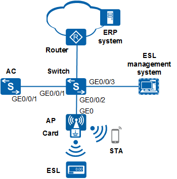
Data Planning
Item |
Data |
|---|---|
Management VLAN |
VLAN 100 |
Service VLAN |
VLAN 101 |
Interworking VLAN of the ESL management system and ESLs |
VLAN 102 |
AC's source interface |
VLANIF 100 |
DHCP server |
The AC functions as a DHCP server to assign IP addresses to APs and STAs. |
IP address pool for APs |
10.23.100.2 to 10.23.100.254/24 |
IP address pool for STAs |
10.23.101.2 to 10.23.101.254/24 |
AP group |
|
Regulatory domain profile |
|
SSID profile |
|
Security profile |
|
VAP profile |
|
Radio profile |
|
AP system profile |
|
AP wired port profile |
|
Configuration Roadmap
- Configure network interworking of the AC, AP, and switch.
- Configure the AP to go online.
- Configure WLAN service parameters.
- Configure interworking between the ERP system and ESL management system.
- Configure interworking between the ESL management system and ESLs.
Configuration Notes
- No ACK mechanism is provided for multicast packet transmission on air interfaces. In addition, wireless links are unstable. To ensure stable transmission of multicast packets, they are usually sent at low rates. If a large number of such multicast packets are sent from the network side, the air interfaces may be congested. You are advised to configure multicast packet suppression to reduce impact of a large number of low-rate multicast packets on the wireless network. Exercise caution when configuring the rate limit; otherwise, the multicast services may be affected.
- In direct forwarding mode, you are advised to configure multicast packet suppression on switch interfaces connected to APs.
- In tunnel forwarding mode, you are advised to configure multicast packet suppression in traffic profiles of the AC.
Configure port isolation on the interfaces of the device directly connected to APs. If port isolation is not configured and direct forwarding is used, a large number of unnecessary broadcast packets may be generated in the VLAN, blocking the network and degrading user experience.
In tunnel forwarding mode, the management VLAN and service VLAN cannot be the same. Only packets from the management VLAN are transmitted between the AC and APs. Packets from the service VLAN are not allowed between the AC and APs.
Procedure
- Set the NAC mode to unified on the AC so that users can connect to the network properly.
<HUAWEI> system-view
[HUAWEI] authentication unified-mode

If the NAC mode is changed from traditional to unified, the unified mode takes effect after you save the configuration and restart the device.
- Configure the switch and AC to enable the AP to communicate with the AC.
# Configure the access switch, and add GE0/0/1 and GE0/0/2 on the switch to VLAN 100 (management VLAN) and VLAN 101 (service VLAN).
<HUAWEI> system-view
[HUAWEI] sysname Switch
[Switch] vlan batch 100 101
[Switch] interface gigabitethernet 0/0/1
[Switch-GigabitEthernet0/0/1] port link-type trunk
[Switch-GigabitEthernet0/0/1] port trunk allow-pass vlan 100 101
[Switch-GigabitEthernet0/0/1] quit
[Switch] interface gigabitethernet 0/0/2
[Switch-GigabitEthernet0/0/2] port link-type trunk
[Switch-GigabitEthernet0/0/2] port trunk pvid vlan 100
[Switch-GigabitEthernet0/0/2] port trunk allow-pass vlan 100 101
[Switch-GigabitEthernet0/0/2] quit
# Configure the AC, and add GE0/0/1 to VLAN 100 and VLAN 101.
<HUAWEI> system-view
[HUAWEI] sysname AC
[AC] vlan batch 100 101
[AC] interface gigabitethernet 0/0/1
[AC-GigabitEthernet0/0/1] port link-type trunk
[AC-GigabitEthernet0/0/1] port trunk allow-pass vlan 100 101
[AC-GigabitEthernet0/0/1] quit
- Configure the AC as a DHCP server to allocate IP addresses to STAs and the AP.
# Configure the AC as the DHCP server to allocate an IP address to the AP from the IP address pool on VLANIF 100, and allocate IP addresses to STAs from the IP address pool on VLANIF 101.
Configure the DNS server as required. The common methods are as follows:- In interface address pool scenarios, run the dhcp server dns-list ip-address &<1-8> command in the VLANIF interface view.
- In global address pool scenarios, run the dns-list ip-address &<1-8> command in the IP address pool view.
[AC] dhcp enable
[AC] interface vlanif 100
[AC-Vlanif100] ip address 10.23.100.1 24
[AC-Vlanif100] dhcp select interface
[AC-Vlanif100] quit
[AC] interface vlanif 101
[AC-Vlanif101] ip address 10.23.101.1 24
[AC-Vlanif101] dhcp select interface
[AC-Vlanif101] quit
- Configure the AP to go online.# Create an AP group to which the APs with the same configuration can be added.
[AC] wlan
[AC-wlan-view] ap-group name ap-group1
[AC-wlan-ap-group-ap-group1] quit
# Create a regulatory domain profile, configure the AC country code in the profile, and apply the profile to the AP group.[AC-wlan-view] regulatory-domain-profile name domain1 [AC-wlan-regulate-domain-domain1] country-code cn [AC-wlan-regulate-domain-domain1] quit [AC-wlan-view] ap-group name ap-group1 [AC-wlan-ap-group-ap-group1] regulatory-domain-profile domain1 Warning: Modifying the country code will clear channel, power and antenna gain configurations of the radio and reset the AP. Continue?[Y/N]:y [AC-wlan-ap-group-ap-group1] quit [AC-wlan-view] quit
# Configure the AC's source interface.[AC] capwap source interface vlanif 100
# Import the AP offline on the AC and add the AP to the AP group ap-group1. Configure a name for the AP based on the AP's deployment location, so that you can know where the AP is located by its name. For example, if the AP with MAC address 60de-4476-e360 is deployed in area 1, name the AP area_1. The default AP authentication mode is MAC address authentication. If the default settings are retained, you do not need to run the ap auth-mode mac-auth command.
In this example, the AP4050DN-E is used and has two radios: radio 0 and radio 1.
[AC] wlan
[AC-wlan-view] ap auth-mode mac-auth
[AC-wlan-view] ap-id 0 ap-mac 60de-4476-e360
[AC-wlan-ap-0] ap-name area_1
Warning: This operation may cause AP reset. Continue? [Y/N]:y
[AC-wlan-ap-0] ap-group ap-group1
Warning: This operation may cause AP reset. If the country code changes, it will clear channel, power and antenna gain configuration s of the radio, Whether to continue? [Y/N]:y
[AC-wlan-ap-0] quit
# After the AP is powered on, run the display ap all command to check the AP status. If the State field displays nor, the AP has gone online.
[AC-wlan-view] display ap all
Total AP information:
nor  : normal          [1]
ExtraInfo : Extra information
P  : insufficient power supply
--------------------------------------------------------------------------------------------------
ID   MAC            Name   Group     IP            Type            State STA Uptime ExtraInfo
--------------------------------------------------------------------------------------------------
0    60de-4476-e360 area_1 ap-group1 10.23.100.254 AP4050DN-E      nor   0   25S    -
--------------------------------------------------------------------------------------------------
Total: 1
- Configure WLAN service parameters.# Create security profile wlan-net and set the security policy in the profile.
In this example, the security policy is set to WPA-WPA2+PSK+AES and password to a1234567. In actual situations, the security policy must be configured according to service requirements.
[AC-wlan-view] security-profile name wlan-net
[AC-wlan-sec-prof-wlan-net] security wpa-wpa2 psk pass-phrase a1234567 aes
[AC-wlan-sec-prof-wlan-net] quit
# Create radio profile wlan-radio2g and configure the VAP to be disabled from 23:00 to 6:00.
[AC-wlan-view] radio-2g-profile name wlan-radio2g
[AC-wlan-radio-2g-prof-wlan-radio2g] auto-off service start-time 23:00:00 end-time 6:00:00
[AC-wlan-radio-2g-prof-wlan-radio2g] quit
# Create SSID profile wlan-net and set the SSID name to wlan-net.[AC-wlan-view] ssid-profile name wlan-net [AC-wlan-ssid-prof-wlan-net] ssid wlan-net [AC-wlan-ssid-prof-wlan-net] quit
# Create VAP profile wlan-net, set the data forwarding mode and service VLAN, and apply the security profile and SSID profile to the VAP profile.[AC-wlan-view] vap-profile name wlan-net [AC-wlan-vap-prof-wlan-net] forward-mode direct-forward [AC-wlan-vap-prof-wlan-net] service-vlan vlan-id 101 [AC-wlan-vap-prof-wlan-net] security-profile wlan-net [AC-wlan-vap-prof-wlan-net] ssid-profile wlan-net [AC-wlan-vap-prof-wlan-net] quit
# Bind VAP profile wlan-net to the AP group and apply the profile to radio 0 and radio 1 of the AP. Bind radio profile wlan-radio2g to the radios.
[AC-wlan-view] ap-group name ap-group1
[AC-wlan-ap-group-ap-group1] vap-profile wlan-net wlan 1 radio 0
[AC-wlan-ap-group-ap-group1] vap-profile wlan-net wlan 1 radio 1
[AC-wlan-ap-group-ap-group1] radio-2g-profile wlan-radio2g radio 0
Warning: This action may cause service interruption. Continue?[Y/N]y
[AC-wlan-ap-group-ap-group1] quit
- Configure interworking between the ERP system and ESL management system. The detailed operations are not described here.
- Configure Layer 2 interworking between the ESL card and ESL management system.
# Add GE0/0/3 on the switch connected to the ESL management system to VLAN 102.
[Switch] vlan batch 102
[Switch] interface gigabitethernet 0/0/3
[Switch-GigabitEthernet0/0/3] port link-type trunk
[Switch-GigabitEthernet0/0/3] port trunk pvid vlan 102
[Switch-GigabitEthernet0/0/3] port trunk allow-pass vlan 102
[Switch-GigabitEthernet0/0/3] quit
# Add GE0/0/2 on the switch connected to the AP to VLAN 102.
[Switch] interface gigabitethernet 0/0/2
[Switch-GigabitEthernet0/0/2] port trunk allow-pass vlan 102
[Switch-GigabitEthernet0/0/2] quit
# Add GE0 on the AP connected to the switch to VLAN 102.
[AC-wlan-view] quit
[AC] vlan batch 102
[AC] wlan
[AC-wlan-view] wired-port-profile name wired1
[AC-wlan-wired-port-wired1] mode root
Warning: If the AP goes online through a wired port, the incorrect port mode configuration will cause the AP to go out of management.
 This fault can be recovered only by modifying the configuration on the AP. Continue? [Y/N]:y
[AC-wlan-wired-port-wired1] vlan tagged 102
[AC-wlan-wired-port-wired1] quit
[AC-wlan-view] ap-group name ap-group1
[AC-wlan-ap-group-ap-group1] wired-port-profile wired1 gigabitethernet 0
[AC-wlan-ap-group-ap-group1] quit
# Set the connection type between the AP and ESL card to ethernet, and add the interface on the AP connected to the ESL card to VLAN 102.
[AC-wlan-view] ap-system-profile name ap-system
[AC-wlan-ap-system-prof-ap-system] card connect-type ethernet
[AC-wlan-ap-system-prof-ap-system] quit
[AC-wlan-view] wired-port-profile name wired2
[AC-wlan-wired-port-wired2] mode endpoint
Warning: If the AP goes online through a wired port, the incorrect port mode configuration will cause the AP to go out of management
. This fault can be recovered only by modifying the configuration on the AP. Continue? [Y/N]:y
[AC-wlan-wired-port-wired2] vlan pvid 102
[AC-wlan-wired-port-wired2] vlan untagged 102
[AC-wlan-wired-port-wired2] quit
[AC-wlan-view] ap-group name ap-group1
[AC-wlan-ap-group-ap-group1] ap-system-profile ap-system
[AC-wlan-ap-group-ap-group1] card 1
[AC-wlan-group-card-ap-group1/1] wired-port-profile wired2
[AC-wlan-group-card-ap-group1/1] quit
[AC-wlan-ap-group-ap-group1] quit
# Restart the AP.
[AC-wlan-view] ap-reset all
Warning: Reset AP(s), continue?[Y/N]:y
- Initialize the ESL card, register ESLs, associate ESL IDs with commodity codes, and configure ESL services. For detailed operations, see the operation guides provided by vendors, which are not described here.
- Verify the configuration.
# The WLAN service configuration is automatically delivered to the AP after it is completed. Run the display vap ssid wlan-net command. If Status in the command output is displayed as ON, the VAP has been successfully created on the AP radios.
[AC-wlan-view] display vap ssid wlan-net
WID : WLAN ID
--------------------------------------------------------------------------------
AP ID AP name RfID WID    BSSID          Status  Auth type     STA   SSID
--------------------------------------------------------------------------------
0     area_1  0    1      60DE-4476-E360 ON      WPA/WPA2-PSK  1     wlan-net
0     area_1  1    1      60DE-4476-E370 ON      WPA/WPA2-PSK  0     wlan-net
------------------------------------------------------------------------------------
Total: 2
# Check the connection type between the AP and ESL card.
[AC-wlan-view] display ap-system-profile name ap-system
...
Card connect type                              : ethernet
...
# Check configuration information about the AP wired port profiles.
[AC-wlan-view] display wired-port-profile name wired1
...
Port work mode                                 : root
Port Tagged VLAN                               : 102
Port untagged VLAN                             : 1
Port PVID VLAN                                 : -
...
[AC-wlan-view] display wired-port-profile name wired2
...
Port work mode                                 : endpoint
Port Tagged VLAN                               : -
Port untagged VLAN                             : 1 102
Port PVID VLAN                                 : 102
...
Configuration Files
Access switch configuration file
#
sysname Switch
#
vlan batch 100 to 102
#
interface GigabitEthernet0/0/1
 port link-type trunk
 port trunk allow-pass vlan 100 to 101
#
interface GigabitEthernet0/0/2
 port link-type trunk
 port trunk pvid vlan 100
 port trunk allow-pass vlan 100 to 102
#
interface GigabitEthernet0/0/3
 port link-type trunk
 port trunk pvid vlan 102
 port trunk allow-pass vlan 102
#
return
AC configuration file
#
 sysname AC
#
vlan batch 100 to 102
#
dhcp enable
#
interface Vlanif100
 ip address 10.23.100.1 255.255.255.0
 dhcp select interface
#
interface Vlanif101
 ip address 10.23.101.1 255.255.255.0
 dhcp select interface
#
interface GigabitEthernet0/0/1
 port link-type trunk
 port trunk allow-pass vlan 100 to 101
#
capwap source interface vlanif100
#
wlan
 security-profile name wlan-net
  security wpa2 psk pass-phrase %^%#>T-{@<QCU9HBYq2^UU6Xz6#)+LWx8GLx]uWo;t!M%^%# aes
 ssid-profile name wlan-net
  ssid wlan-net
 vap-profile name wlan-net
  service-vlan vlan-id 101
  ssid-profile wlan-net
  security-profile wlan-net
 regulatory-domain-profile name domain1
 radio-2g-profile name wlan-radio2g
  auto-off service start-time 23:00:00 end-time 06:00:00
 ap-system-profile name ap-system
  card connect-type ethernet
 wired-port-profile name wired1
  mode root
  vlan tagged 102
 wired-port-profile name wired2
  mode endpoint
  vlan pvid 102
  vlan untagged 102
 ap-group name ap-group1
  ap-system-profile ap-system
  wired-port-profile wired1 gigabitethernet 0
  regulatory-domain-profile domain1
  radio 0
   radio-2g-profile wlan-radio2g
   vap-profile wlan-net wlan 1
  radio 1
   vap-profile wlan-net wlan 1
  card 1
   wired-port-profile wired2
 ap-id 0 ap-mac 60de-4476-e360
  ap-name area_1
  ap-group ap-group1
#
return