Using Front Mounting Brackets or Cable Management Frames and Rear Mounting Brackets
Context
This installation method applies to S5710-HI switches.
Follow these precautions before or during the installation:
- Ensure that the cabinet is stable and meets the requirements specified in Checking the Cabinet or Rack.
- Leave sufficient vertical space in the cabinet or rack for the switch.
- Leave at least 50 mm (2.0 in.) clearance around the switch for heat dissipation. Do not install a switch with its air intake vent facing or close to the air exhaust vent of other devices.
- To install multiple switches in one cabinet or rack, leave at least 1 U (1 U = 44.45 mm) between switches that use natural heat dissipation. For switches that use forced or intelligent air cooling, the recommended spacing between them is 1 U.
- Align the mounting brackets on the left and right mounting rails. If they are not on a horizontal line, forcibly mounting the switch may distort the chassis.
- To install an S5710-HI switch, install front mounting brackets or cable management frames and rear mounting brackets on the switch. If guide rails are installed in the cabinet, install only front mounting brackets or cable management frames on the switch.
- If all ports on the switch need to be used, many cables will be connected to the switch. Cable management frames are recommended in this case.
Tools and Accessories
- ESD wrist strap or ESD gloves
- Phillips screwdriver
- Flat-head screwdriver
- Measuring tape
- Floating nuts (eight per switch, purchased separately)
- M4 screws (sixteen per switch)
- M6 screws (eight per switch, purchased separately)
- Front mounting brackets or cable management frames (two per switch)
- Rear mounting brackets (two per switch)
- Rear mounting bracket guide rails (two per switch)

The M4 screws, front and rear mounting brackets, cable management frames, and rear mounting bracket guide rails are included in the installation accessory package.
Procedure
- Wear an ESD wrist strap or ESD gloves. When wearing an ESD wrist strap, ensure that it is in close contact with your wrist and grounded properly.
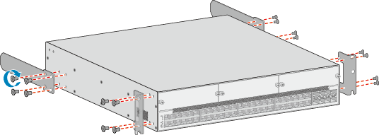
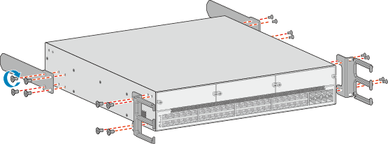
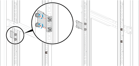
- Use M4 screws to attach front mounting brackets or cable management frames and rear mounting brackets to the switch. Figure 1 and Figure 2 show the mounting brackets and cable management frames of an S5710-HI and associated installation methods.
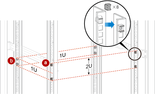
- Install floating nuts on the mounting rails of the cabinet. See Figure 3.
- Determine the installation position of the switch and use a flat-head screwdriver to install two floating nuts on each front mounting rail accordingly. Leave a gap of 2 U between the two floating nuts and ensure that they are level with those on the other front mounting rail.
- Install two floating nuts on each rear mounting rail. Leave a gap of 1 U between the two floating nuts. Ensure that the lower floating nuts on the four mounting rails are level with one another.
- Use a measuring tape to measure the distance between the front and rear mounting rails.
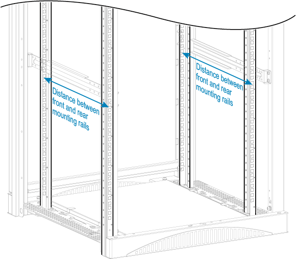
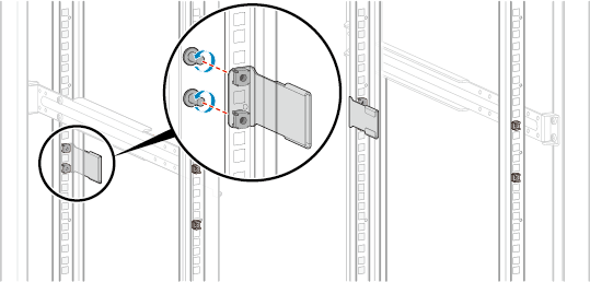
- Install two rear mounting bracket guide rails on the rear mounting rails. The distance between the front and rear mounting rails determines the direction in which the guide rails should face. See Figure 4 and Figure 5.
- Align the holes on the guide rails with the floating nuts on the rear mounting rails.
- Secure the rear mounting bracket guide rails with M6 screws (two on each side) using a Phillips screwdriver.
- Install the switch in the cabinet.
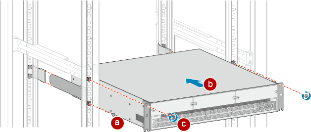
- If you have installed front and rear mounting brackets on the switch, perform the following steps:
- Place M6 screws on the two lower floating nuts on the front mounting rails. Reserve a clearance between the top of the screws and the floating nuts for installing front mounting brackets.
- Align the rear mounting brackets with the rear mounting bracket guide rails. Then, gently slide the switch into the cabinet along the guide rails.
- Align the holes on the front mounting brackets with floating nuts on the front mounting rails, place the recesses at the bottom of the front mounting brackets on the M6 screws, and then use a Phillips screwdriver to tighten the M6 screws.
In Figure 6, the distance between front and rear mounting rails is 545-655 mm (21.5-25.8 in.).
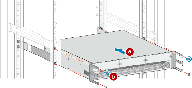
- If you have installed cable management frames and rear mounting brackets on the switch, perform the following steps:
- Align the rear mounting brackets with the rear mounting bracket guide rails. Then, gently slide the switch into the cabinet along the guide rails.
- Align the holes on the cable management frames with the floating nuts on the front mounting rails, and secure the cable management frames with M6 screws using a Phillips screwdriver.

Do not hold the cable management frames to move the switch as doing so may damage the cable management frames.
In Figure 7, the distance between front and rear mounting rails is 545-655 mm (21.5-25.8 in.).
- If you have installed front and rear mounting brackets on the switch, perform the following steps: