Connecting Power Cables
Context
The S2700, S3700, S5700, and S6700 series switches have a built-in power supply unit and support pluggable or independent power modules. The required power cables and their connection methods vary according to the power modules used on the switches.
For non-S5720I-SI series switches:
- To connect to an AC power outlet, the switch must have a built-in AC power supply unit or use a pluggable AC power module, which must be connected using an AC power cable complying with local standards.
- To connect to an AC power distribution unit (PDU), the switch must have a built-in AC power supply unit or use a pluggable AC power module, which must be connected using a C13 straight female to C14 straight male AC power cable.
- To connect to a DC power distribution box, the switch must have a built-in DC power supply unit or use a pluggable DC power module, which must be connected using DC power cables.

The AC power cable parameters vary in different countries or regions. The figures in this section are only for reference.
For a desk-mounted DC switch, use 18 AWG (1 mm2) DC power cables with a maximum insulation diameter of no more than 2.1 mm (0.08 in.). UL1007 DC power cables are recommended.
For the S5720I-SI series switches and the PAC-260WA-E or PAC240S56-CN, Phoenix connectors and power cables are required.

There is a risk of electrical shock when connecting power cables. To avoid electric shock, do not connect power cable while the power is on.

- Power cables of the switch must be routed indoors or buried underground if they are led in from the outside. Do not aerially route the power cables outdoors.
- Do not power on the switch until you finish installing the switch and connecting all cables.
- Power cables delivered with the switch are for use with this switch only.
Tools and Accessories
- ESD wrist strap or ESD gloves
- Phillips screwdriver
- (Optional) AC terminal locking latch
- (Optional) Wire stripper
Procedure
- Wear an ESD wrist strap or ESD gloves. When wearing an ESD wrist strap, ensure that it is in close contact with your wrist and grounded properly.
- Turn off the external power supply system for the switch.
- Turn off the power switch on the switch or power module.
Skip this step if there is no power switch on the switch or power module.
- Connect a power cable to the switch or power module.
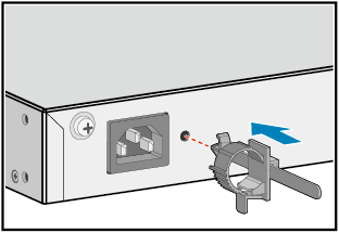
- To connect an AC power cable to a built-in AC power supply unit or AC power module (except for the S5720I-SI), perform the following steps (built-in AC power supply used as an example):
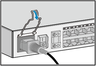
(Optional) Install the AC power cable locking strap.
The AC power cable locking strap is not delivered with the switch.
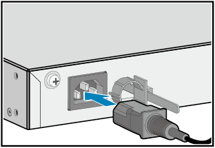
Insert the AC power cable plug into the power socket on the switch or AC power module.
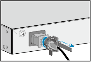
(Optional) If an AC power cable locking strap is installed, adjust its size to fit the AC power cable plug.
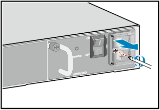
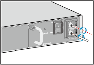
- To connect DC power cables to a built-in DC power supply unit or a 150 W or 170 W DC power module (except for the S5720I-SI), perform the following steps (150 W DC power module used as an example):
Use a Phillips screwdriver to loosen the screw on the DC terminal protective cover, and then remove the protective cover.
Use the Phillips screwdriver to remove the screws on the two DC terminals.
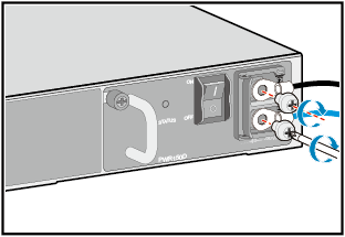
Secure the DC power cables to the DC power module with the screws you removed in step b.
Ensure the correct polarity of connected cables. If you use DC power cables delivered from Huawei, connect the -48 V return ground cable (black) to the RTN(+) terminal, and connect -48 V power cable (blue) to the NEG(-) terminal.
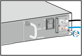
Install the protective cover and fasten the screw.
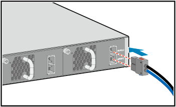
To connect DC power cables to a 350 W, 650 W, or 1000 W DC power module, insert the DC power cable plug into the power sockets on the DC power module. Ensure that the positive and negative poles of the plug are connected to the positive and negative sockets, respectively.
For the AC input of the S5720I-SI or the PAC-260WA-E or PAC240S56-CN power module, connect the power cables as follows:
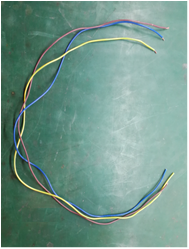
- If the AC power cables are semi-finished cables:
Cut the power cables to a proper length based on the installation position of the switch in the cabinet.
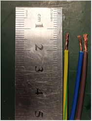
Use a wire stripper to peel 7-10 mm length of insulation off one end of the power cables.
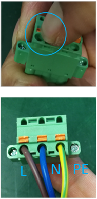
Press and hold the spring in the middle of the Phoenix connector, insert the live wire (L), neutral wire (N), and ground wire (PE) into the terminals according to the sequence shown in the following figure, and release the spring to lock the cables.
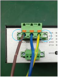
Insert the Phoenix connector into the AC input port on the switch or power module, and tighten the screws on both sides of the Phoenix connector.
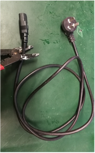
- If a three-pin AC power plug purchased by the customer is used, connect the power cable to the three-pin AC power plug as follows:
- Use a tool (such as a screwdriver, depending on the plug type) to open the three-wire AC power plug.
- Use a wire stripper to remove the required length of insulation (depending on the plug type) off one end of the power cable.
- Secure the live wire (L), neutral wire (N), and ground wire (PE) to the corresponding L, N, and PE terminals in the power plug.
- Use the tool to reassemble the power plug.
- Ensure the live wire (L), neutral wire (N), and ground wire (PE) are securely installed in the correct terminals. Pull each wire to check whether they are securely installed.
- Ensure that no metal wire is exposed outside the power plug.
- If the AC power cables are finished cables:
Cut off the C13 straight female of the finished AC power cable.
Use a wire stripper to peel 40 mm length of the outer sheath and then peel 7-10 mm length of inner insulation.
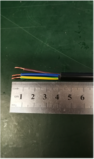
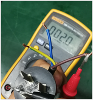
Use a multimeter to distinguish the live wire (L), neutral wire (N), and ground wire (PE). Generally, L is red, N is blue, and PE is yellow-green.
Press and hold the spring in the middle of the Phoenix connector, insert the live wire (L), neutral wire (N), and ground wire (PE) into the terminals according to the sequence shown in the following figure, and release the spring to lock the cables.
Insert the Phoenix connector into the AC input port on the switch or power module, and tighten the screws on both sides of the Phoenix connector.
There is a risk of electric shock when handling the Phoenix connector. To avoid electric shock, ensure that the L/N/PE wires are connected in sequence.
After power cables are connected to the Phoenix connector, ensure that copper conductors are not bent and there are no exposed metal parts.
Ensure that power cables are securely connected to the Phoenix connector (you can pull the cables one by one for check).
Figure 2 Connections of AC input power cables for the PAC-260WA-E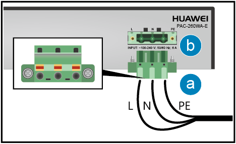 Figure 3 Connections of AC input power cables for the PAC240S56-CN
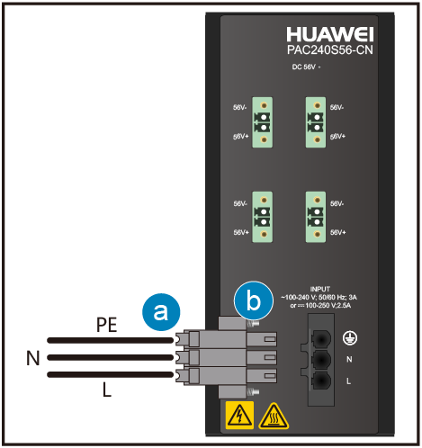
- If the AC power cables are semi-finished cables:
For the DC input of the S5720I-SI or DC output of the PAC-260WA-E power module, connect the power cables as follows:
- Use a wire stripper to peel about 7 mm length of insulation coating off one end of the positive and negative cables. Press and hold the spring in the middle of the Phoenix connector, insert the bare wires of the power cable into the socket according to the sequence shown in the figure, and release the spring to lock the cable.
- Insert the Phoenix connector into the DC input port on the switch or the DC output port on the power module, and tighten the screws on both sides of the Phoenix connector.
Figure 4 Connections of DC output power cables for the PAC-260WA-E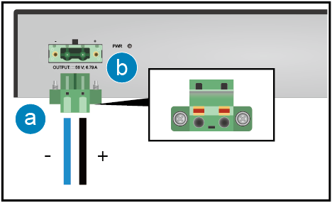
For the DC output of the PAC240S56-CN power module, connect the power cables as follows:
- Use a wire stripper to peel about 7 mm length of insulation coating off one end of the positive and negative cables. Insert the bare wires of the power cable into the Phoenix connector according to the sequence shown in the figure, and tighten the screws to lock the cable.
- Insert the Phoenix connector into the DC output port on the power module, and tighten the screws on both sides of the Phoenix connector.
Figure 5 Connections of DC output power cables for the PAC240S56-CN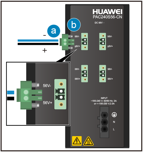
- To connect an AC power cable to a built-in AC power supply unit or AC power module (except for the S5720I-SI), perform the following steps (built-in AC power supply used as an example):
- Connect the power cables to the external power supply system.
For non-S5720I-SI series switches:
- If you are using the standard AC power cables for your geographical location, connect them to an AC power strip or power distribution box.
- If you are using C13 straight female to C14 straight male AC power cables, connect them to a PDU.
- If you are using DC power cables, connect them to a DC power distribution box. Ensure correct connections of the positive and negative power cables.
For the AC input of the S5720I-SI or the PAC-260WA-E, the 220 V mains power is used.
For the PAC240S56-CN, the 220 V AC or 240 V DC power is used.
Follow-up Procedure
Complete a post-installation check before powering on the switch. For the post-installation checklist, see Post-installation Checks. For details about how to power on the switch, see Powering on a Switch for the First Time.