Connecting Ethernet Cables
Context

- Before deploying Ethernet cables, test their electrical connectivity.
- If Ethernet cables of the switch need to be routed outdoors, bury them underground or put them through steel pipes to avoid lightning strikes to the switch. Do not aerially route Ethernet cables outdoors.
- Keep signal cables more than 10 cm away from power cables.
- When a switch with 48 optical ports and copper modules is installed in a 600 mm deep cabinet, only Category 5 unshielded twisted pairs can be used.
- When a switch with 48 electrical ports is installed in a 600 mm deep cabinet, only Category 5 unshielded twisted pairs can be used.
If a switch does not support or is not installed with a rear card, the Ethernet cables used on its electrical ports and the distance between the switch front panel and cabinet front door must meet the requirements described in Table 1.
Network Cable Type |
Distance (Excluding the Length of a Copper Module) Between the Switch Front Panel and Cabinet Front Door (X) |
|---|---|
| Category 5 unshielded twisted pair | X ≥ 80 mm (3.1 in.) |
| Category 5 shielded twisted pair | X ≥ 110 mm (4.3 in.) |
| Category 6 twisted pair | X ≥ 120 mm (4.7 in.) |

- For a switch with 48 electrical ports, route Ethernet cables from both sides of the cabinet. Specifically, route cables to the first 24 ports from the left of the cabinet, and to the last 24 ports from the right of the cabinet.
- If the cabinet is densely cabled from both sides, it is recommended to reserve 1 U of clearance below the switch for a cable tray. Route the Ethernet cables through the cable tray and bundle the cables on both sides of the cabinet, to ensure that the weight of the cables is supported by the cabinet.
- In a cabinet deeper than 600 mm, the Ethernet cables used on its electrical ports and the distance between the switch front panel and cabinet front door must meet the requirements described in Table 1. There is no specific requirement for the distance between the switch rear panel and cabinet rear door.
- In a 600 mm deep cabinet, the Ethernet cables used on its electrical
ports, the optical fibers used on the rear card, and the distances
between the switch panels and cabinet doors must meet the requirements
described in Table 2.
Table 2 Requirements for Ethernet cables and optical fibers Network Cable Type
Distance (Excluding the Length of a Copper Module) Between the Switch Front Panel and Cabinet Front Door (X) Distance Between the Switch Rear Panel and Cabinet Rear Door (Y) Ultra-short Pigtail Short Pigtail Regular Fiber or QSFP+ Fiber Category 5 unshielded twisted pair 80 mm (3.1 in.) < X < 100 mm (3.9 in.) Y ≥ 60 mm (2.4 in.) Y ≥ 72 mm (2.8 in.) Y ≥ 80 mm (3.1 in.) Category 5 shielded twisted pair X = 110 mm (4.3 in.) Y ≥ 60 mm (2.4 in.)
Route Ethernet cables from both sides of the cabinet.
Y ≥ 72 mm (2.8 in.)
Route Ethernet cables from both sides of the cabinet.
Cannot be used together with Category 5 shielded twisted pair Ethernet cables. Category 6 twisted pair X = 120 mm (4.7 in.) Y ≥ 60 mm (2.4 in.)
Route Ethernet cables from both sides of the cabinet.
Cannot be used together with Category 6 twisted pair Ethernet cables. Cannot be used together with Category 6 twisted pair Ethernet cables.
Category 6A STP or higher category twisted pairs are recommended for 10GBASE-T ports. Category 6A STP and Category 7 twisted pair cables can prevent alien crosstalk. These cables can be used together with other types of cables and must be bundled on supporting objects because they are heavy.
Strong interference may cause a bit error rate of no more than 10-7 on MultiGE ports (10GBASE-T and IEEE802.3bz). To prevent this problem, keep the switch away from interference sources or take adequate interference shielding measures. Triggering the fast retrain function will cause a large number of bit errors in a period of around 30 ms.
Procedure
- Determine the number and type of ports to be connected and plan the cabling routes.
- Obtain the desired quantity and lengths of Ethernet cables.
- Attach temporary labels to both ends of each Ethernet cable and number them corresponding to port numbers. For details, see Engineering Labels for Network Cables.
- Route the Ethernet cables, arrange the cables in the cabinet, and then install cable connectors. Cable connectors made onsite must be securely attached and comply with related standards.
- Wear an ESD wrist strap or ESD gloves. When wearing an ESD wrist strap, ensure that it is in close contact with your wrist and grounded properly.
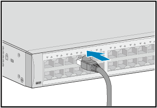
- Connect the cable connectors to the ports, matching the
numbers on the Ethernet cables to those on the ports. After connecting
the cables, verify that they are all correctly connected.
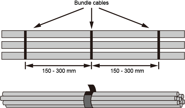
- Arrange the Ethernet cables so that they are
parallel, and then bundle them with cable ties loosely according to Table 3. Use a cable tie gun to cut off
redundant cable ties. The use of protective pads under the cable ties
is recommended, as shown in Figure 1.
A bundle cannot have more than 24 cables. A bundle of no more than 12 cables is recommended.
- Replace all the temporary labels on the Ethernet cables with permanent labels.