Example for Implementing eSight-based Zero Touch Provisioning for the Campus Headquarters
Prerequisites
- The root device and devices to be deployed support zero touch provisioning. For details about device types, see eSight Release Notes.
- A root device has been added to eSight for management and can communicate normally with eSight through SNMP and Telnet.
- A DHCP server has been configured and uses the root device as a gateway.
- Input or output is not allowed on Console interfaces during zero touch provisioning.
- The device software package, license file, and patch file have been prepared and uploaded to eSight. If not, choose to upload the files.
Networking Requirements
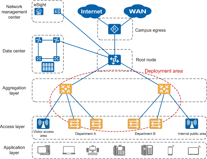
On the wired campus network of company M, there are lots of devices at the aggregation and access layers. Traditionally, the network design, and software/hardware installation and commissioning are performed by different personnel. Each device to be deployed needs to be manually associated with provisioning files through a USB flash drive. The configuration is complex and has low efficiency. Jack, the network administrator of the company, requires that eSight implement unified zero touch provisioning for aggregation and access devices to reduce management cost.
In the following figure, the red circle specifies the devices to be deployed. The eSight software version is V300R003C20.
Configuration Roadmap
- Select a root device and configure VLAN 1 as a pass VLAN on the root device.
- Configure the root device as a DHCP server.
- Plan the network topology on the Topo Plan-based Provisioning page.
- Prepare configuration files for devices to be deployed.
- Configure mappings between the configuration files and devices.
- Install and power on devices according to the planned topology (performed by the hardware commissioning personnel).
- Check whether the actual physical topology is consistent with the planned topology on eSight (performed by the software commissioning personnel).
- Trigger provisioning if the topologies are consistent (performed by the software commissioning personnel). The devices to be deployed then download corresponding files.
Data Plan
Device Type |
Device IP Address |
Downstream Port 1 |
Downstream Port 2 |
|---|---|---|---|
S5720–56C-PWR-HI-AC |
10.137.58.61 |
GE0/0/1 |
GE0/0/2 |
Device Type |
IP Address |
Upstream Port |
Downstream Port 1 |
Downstream Port 2 |
|---|---|---|---|---|
S5720–32C-HI-24S-AC |
10.137.58.1 |
GE0/0/1 |
GE0/0/2 |
GE0/0/3 |
S5720–32C-HI-24S-AC |
10.137.58.2 |
GE0/0/1 |
GE0/0/2 |
GE0/0/3 |
Device Type |
IP Address |
Upstream Port |
|---|---|---|
S2750–28TP-EI-AC |
10.137.58.3 |
GE0/0/1 |
S2750–28TP-EI-AC |
10.137.58.4 |
GE0/0/1 |
S2750–28TP-EI-AC |
10.137.58.5 |
GE0/0/1 |
S2750–28TP-EI-AC |
10.137.58.6 |
GE0/0/1 |
Procedure
- Specify VLAN 1 as a pass VLAN on the root device (the configuration is not provided here).
- Configure the root device as a DHCP server. For details, see Configuring a DHCP Server.
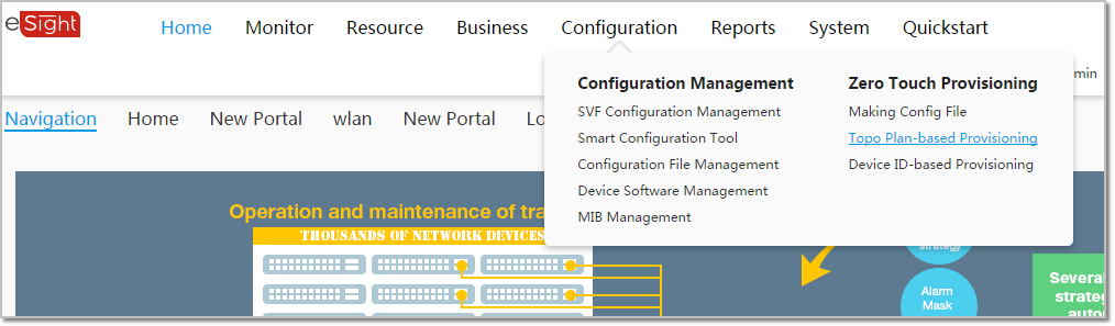
- Plan the network topology on the Topo Plan-based Provisioning page.
- Choose .
- Right-click a blank area in the main topology and select Create Task.
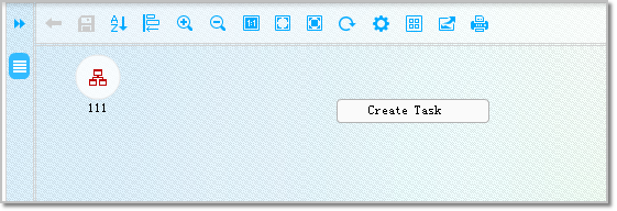
- Double-click Task for Department AB. The subview page of the task is displayed.
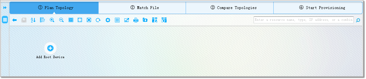
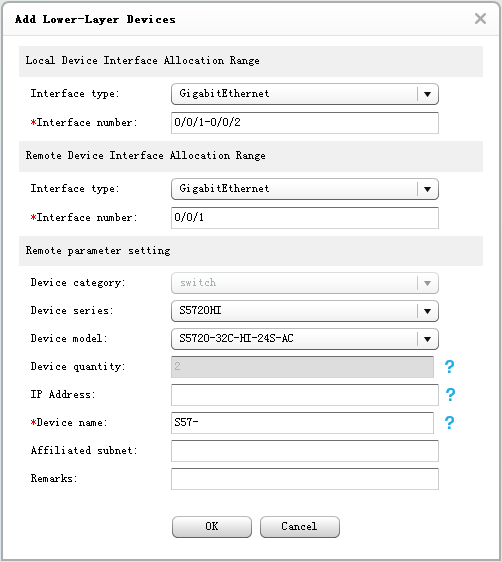
- Add an aggregation device: On the Plan Topology page, right-click the root device icon and choose . In the Add Lower-Layer Devices dialog box that is displayed, enter the following parameters and click OK.
- The page displays the aggregation devices that have been created. Click
 on the toolbar and select From Top to Bottom. The page displays the root device and aggregation devices in the sorted order.
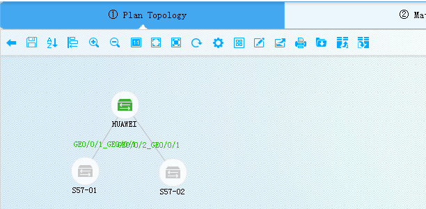
- Right-click the S57–00 icon and choose . In the Add Lower-Layer Devices dialog box that is displayed, enter the following parameters and click OK.

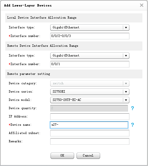
- Right-click the S2750–01 icon and choose . In the Add Lower-Layer Devices dialog box that is displayed, enter the following parameters and click OK.
- Click on the toolbar and select From Top to Bottom. The page displays the root device, aggregation devices, and access devices in the sorted order.

- Choose .
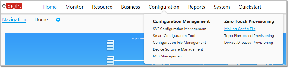
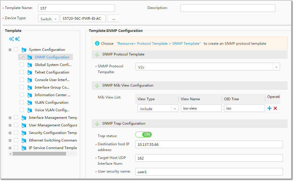
- Prepare configuration files for devices to be deployed.
- Choose .
- Click Create, enter the following parameters, and click Next. Click OK. The configuration file is created for the aggregation devices.
- Choose .
- Configure mappings between the configuration file, software package, and license file and device.
- Drag to select the four access devices, right-click the access device icon, and select Match Provisioning File. Select the correct provisioning files and click OK.
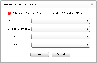
- Drag to select the four access devices, right-click the access device icon, and select Match Provisioning File. Select the correct provisioning files and click OK.
- Install and power on devices according to the planned topology (performed by the hardware commissioning personnel).
- Check whether the actual physical topology is consistent with the planned topology on eSight (performed by the software commissioning personnel). After topology collection is enabled, eSight collects the network topology of the provisioning area from the root node, maps the collected topology with the planned topology, and shows the differences for users to correct.
- Switch to the Compare Topologies page. The page displays the topology comparison result at the bottom.
- Trigger provisioning if the topologies are consistent (performed by the software commissioning personnel). The devices then download corresponding files.
- Switch to the Start Provisioning page. Drag to select devices to be deployed, and right-click and select Start to Deploy.
- The page displays the provisioning delivery result. Drag to select all devices to be deployed, and right-click and select Active. The devices restart and load the new configuration file. The provisioning delivery is complete.