Installing Optical Fibers

- Wear an ESD wrist strap or ESD gloves before installing optical modules.
- The bending radius of a single-mode G.657A2 optical fiber is greater than or equal to 10 mm, and the bending radius of a multi-mode A1b optical fiber is greater than or equal to 30 mm.
- Cover empty optical interfaces and idle optical modules with dust caps.
- Do not bundle optical fibers too tightly. You must be able to conveniently remove a single fiber from the bundle.
- Properly fix optical fibers onto the cabinet columns to prevent impact on the surrounding devices.
- Attach temporary labels to both ends of each optical fiber.
- Arrange optical fibers into a bundle and feed them through the corrugated pipe.
- Wrap adhesive tapes on both ends of the corrugated pipe to protect it from cuts.
- Route the corrugated pipe along the cable ladder.
- Insert the corrugated pipe through the dedicated cable hole on the cabinet top to the cabinet about 100 mm and tie the pipe to the cabinet.Figure 1 Inserting the corrugated pipe

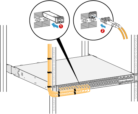
- Install the optical module, as shown in step 1 in Figure 2.
- Route optical fibers along the cable tray, remove the dust caps from the optical modules and optical fiber interfaces. Then connect the end of each optical fiber to the corresponding optical interface, as shown in step 2 in Figure 2.
- Connect the other end of each optical fiber to the ODF.
- Bundle optical fibers with binding straps at an interval of 150 mm and fasten the optical fibers to the cable tray.
- Attach permanent labels 20 mm from both ends of each optical fiber.