DC Power Distribution Guide

Do not install power cables when the power is on. This is to avoid injuries.
Figure 1 Schematic diagram of the DC power distribution

DC Power Supply System
For cable specifications, see "Hardware Description"-Equipment Cables-Power Cables.
Item |
Description |
Remarks |
|---|---|---|
Circuit breaker of each channel |
≥32 A NOTICE:
The circuit breaker current must not be greater than the maximum derating current of the device. |
- |
Installing Power Cables
- Connect the power cord to the power connector.
- Attach temporary labels to both ends of each power cable.
- Route power cables along the cable ladder and lay them on the chassis.
- Take off the plastic cover from each power module, connect one end of each power cable to the corresponding terminal and the other end to the PDF.Figure 2 Installing the Power Cables
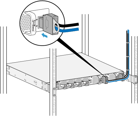
- Use cable ties to bundle cables every 150 mm upwards from the bottom and fasten the cables to the cable tray.
- Attach permanent labels 20 mm from both ends of each power cable.

To ensure that the power cable is long enough, perform the following steps to install a power cable:
- Prepare a power cable a little longer than the distance between the power module and PDF.
- Install a terminal on one end of the power cable and connect the terminal to the device.
- Connect power cables to the positive and negative electrodes securely. Otherwise, the power test result is inaccurate.
- Route the power cable, bind it to the cable tray, and cut any excess length of the cable. Install a terminal on the other end of the power cable and connect the terminal to the PDF.