Assembling the OT Terminal and Power Cable
Background
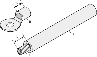
Figure 1 shows the components of an OT terminal and a power cable.
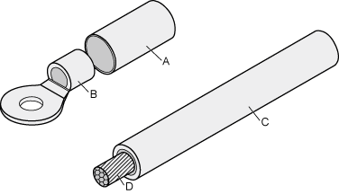
A. Heat shrink tubing |
B. Bare crimping terminal |
C. Insulation |
D. Conductor |
Procedure
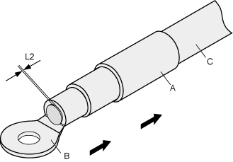
Based on the cross-sectional area of the cable conductor, strip a length of insulation coating C to expose the conductor D of length L1, as shown in Figure 2. The recommended values of L1 are listed in Table 1.

- When you strip a power cable, do not damage the conductor of the cable.
- If the bare crimping terminal is not provided by Huawei, the value of L1 is 1 mm (0.04 in.) to 2 mm (0.08 in.) greater than the value of L.
Table 1 Mapping between the cross-sectional area of the conductor and the value of L1 Cross-Sectional Area of Conductor (mm2 (in.2))
Value of L1 (mm (in.))
Cross-Sectional Area of Conductor (mm2 (in.2))
Value of L1 (mm (in.))
1 (0.002)
7 (0.28)
10 (0.015)
11 (0.43)
1.5 (0.002)
7 (0.28)
16 (0.025)
13 (0.51)
2.5 (0.004)
7 (0.28)
25 (0.039)
14 (0.55)
4 (0.006)
8 (0.31)
35 (0.054)
16 (0.63)
6 (0.009)
9 (0.35)
50 (0.077)
16 (0.63)

If you are proficient in assembling OT terminals and power cables, you can obtain the value of L1 by comparing the part to be crimped with the power cable.
Put the heat-shrinkable (A) tubing onto the bare crimping terminal, as shown in Figure 3.
Put the OT terminal B onto the exposed conductor, and ensure that the OT terminal is in good contact with the insulation coating C, as shown in Figure 3.
After the conductor is fed into the OT terminal, the protruding part of the conductor, or L2 in Figure 3, must not be longer than 2 mm (0.08 in.).
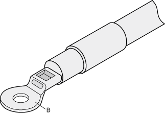
Crimp the joint parts of the bare crimping terminal and the conductor, as shown in Figure 4.
The shapes of crimped parts may vary with the crimping dies.
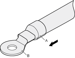
Push the heat shrink tubing (A) toward the connector until the tube covers the crimped part, and then use a heat gun to heat the tube, as shown in Figure 5.
Stop heating the shrink tubing when the connector is securely locked in the shrink tubing. Do not heat the shrink tubing too long as this may damage the insulation coating.